Controlling the Powers that be
or, sometimes too much time goes by
Converting a cheap WiFi connected smart plug to HomeAssistant
I once had my power supply company install a couple of solar panels for a small grid-tied setup, and as part of that deal they were providing a couple of energy monitoring and controlling smart plugs that connected through Zigbee to their own gateway device. Now, it should come as no surprise I don't quite like the "cloud" infrastructure where details of how, where and which data are collected are opaque to the user, i.e. me.
Usually that means I simply will not use said devices, though of course there are exceptions. In this case it was actually simple, I just paired the plugs to my Zigbee enabled Home Assistant instance and presto, everything just worked, power monitoring and controlling.
And having used the two provided plugs I was hooked (see what I did there?), and wanted more, but being a cheapskate at heart I searched high and low for the best possible deal.
After seeing several references to these Energeeks / GoSund WiFi enabled smart power plugs being supported by Tasmota or ESPHome it was just a question of getting one to try, as the price was really, really good. I ended up getting one Energeeks SP112.
A simple firmware update wouldn't justify a journal entry
Of course, having received it, the first thing I did was open the thing up and check the internals. Normally I would first test the device as it comes, just to assert everything works as it should, but I did not want to install the Energeeks app, so other than make sure the thing wouldn't blow a fuse once connected to mains, I did no other testing... I would eventually regret this, of course.
Anyway, it wasn't completely straightforward to disassemble the thing, and nor should it be as to safely allow up to 16A to move from the plug to the PCB (at least I assume the current sense is happening on the full load on the PCB) some serious connection is needed, and that was not easy to de-solder with my USB powered soldering iron. I love the thing, but it was just not the tool for the job, though though perseverance and some plastic melted from a fuse on the board, eventually I got it taken apart.
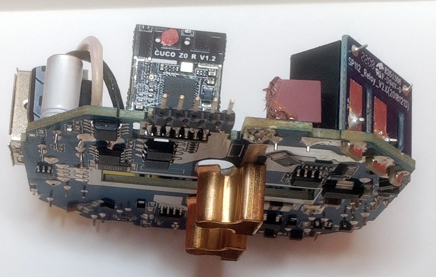
The PCB looked quite good, and there were even breakout pads for the serial port, along with power, ground and even GPIO0 which is used on the ESP8266 and alike to get the module into programming mode by pulling that pin down to ground on bootup. It all seemed solid.
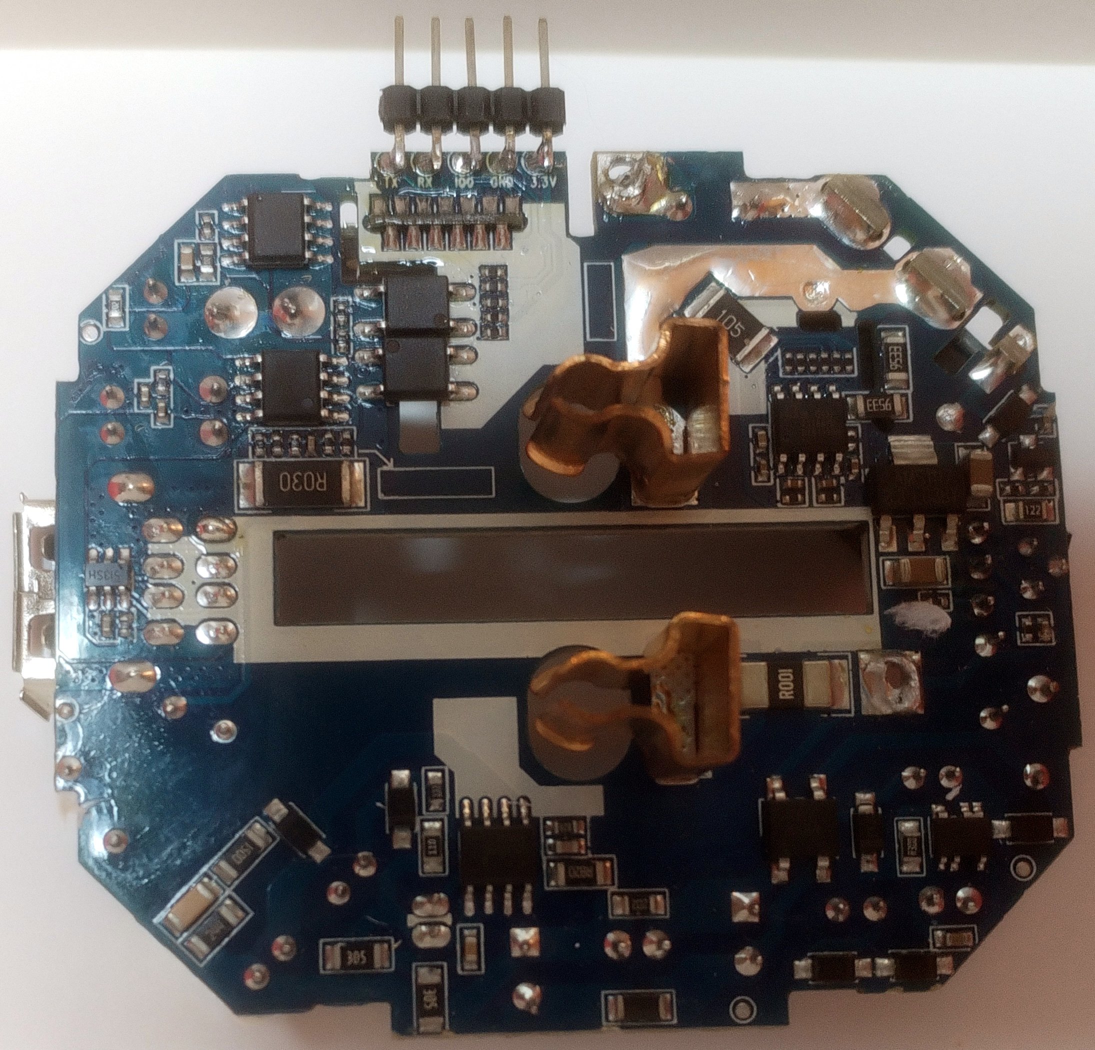
The pads for programming received a pin header to facilitate things and... I could not, for the life of me, get the WiFi module to say anything. So I removed the module and from it the metal shield to see what chip I was working with, or against.
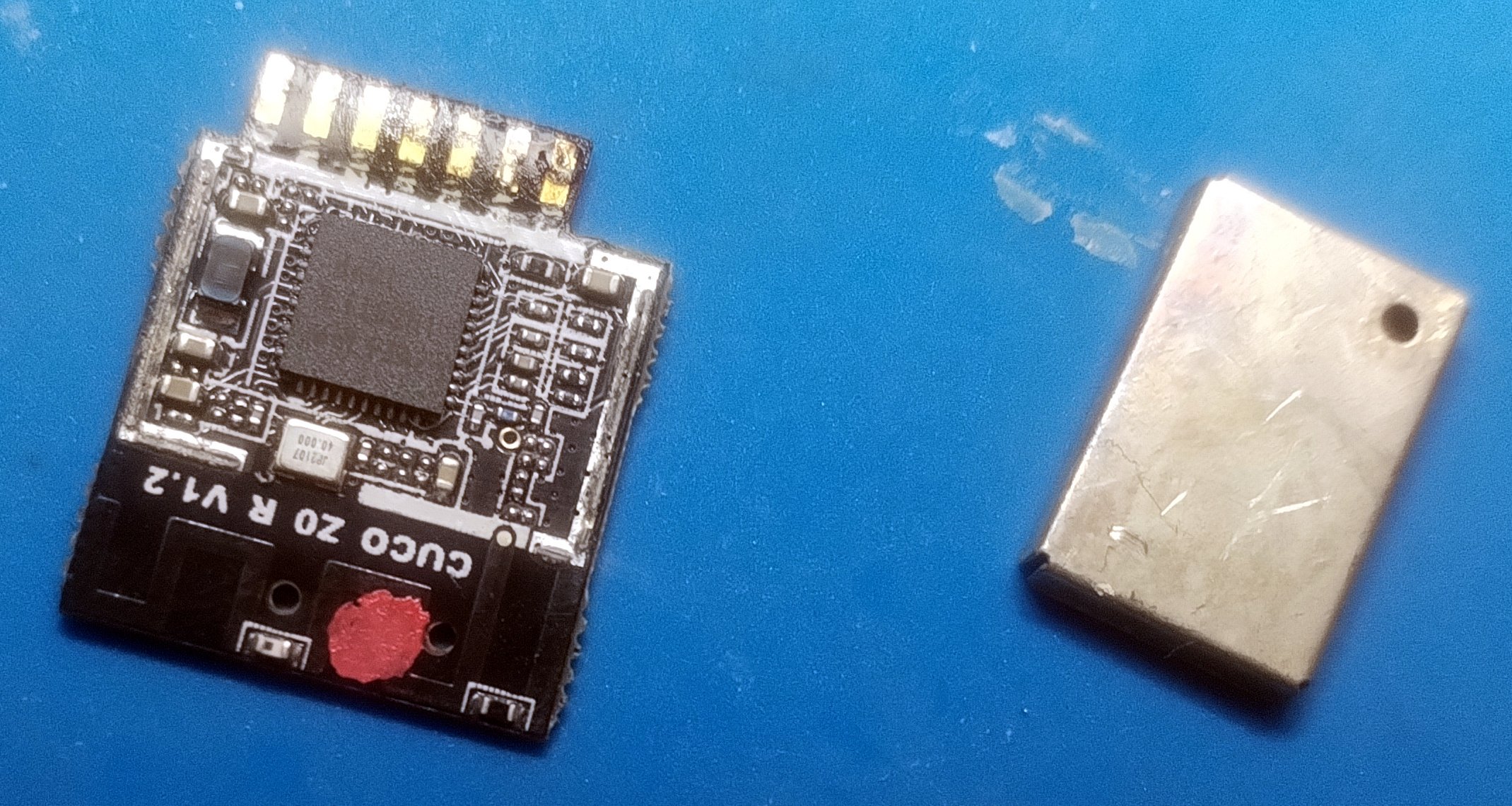
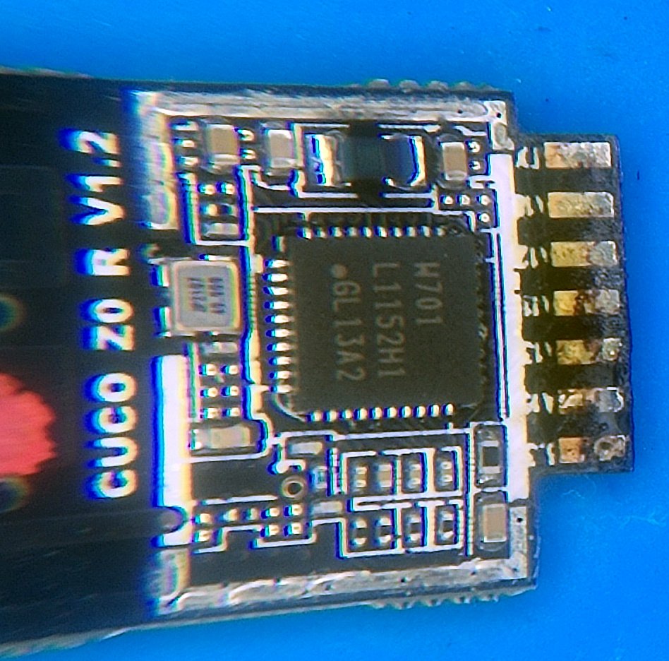
"W701 L1152H1 GL13A2", right?
I believe the chip says "W701 L1152H1 GL13A2" but though I tried several combinations of that, I could not find any potential matches. So I resorted to the PCB silkscreen reference "CUCO Z0 R V1.2" and that was a hit. Not a huge hit, but there were some references that obviated my issue for sure, like this and this.
This was a long time ago, I no longer recall how I got there, but looking at the Tasmota documentation I stumbled somehow on the WT-01N chip, which looked exactly like the perfect replacement and so I ordered a few. That took weeks to arrive, followed by my getting busy with some other projects and this was left on the "to do bench" for quite some time.
A few weeks ago I was putting some things away, doing my 5 minutes of organization I force myself to do at least twice a year and there it was, a box with the shell and the guts of the plug, waiting for some TLC. It did take me a while to find the WT-01N modules, but once I did it immediately jumped out that I had not done my due diligence back when this first started for sure, as the module I ordered has 11 pins total, 6 on one side and 5 on the other, and the CUCO one I'm replacing has 13, 7 and 6 respectively. This should have been obvious...
So, I set out to find another module I could use and this time I came across this adapter PCB which converted an ESP-M2 module to be used in place of the CUCO one. Great, but I happen to have a few ESP8266-MOD modules around, basically knock-offs of the ESP-12F, and I haven't played around with PCBs in a while, so I set off to tweak the design from this Chris Klinger fellow to accommodate those.
I do love the routing part
Designing PCBs is very much like a puzzle game to me, and while I am not very good at it, I actually am aware I don't know all the rules to this game, it does provide me with a good level of enjoyment to find the best (as far as I know) solution to connect everything that needs connecting.
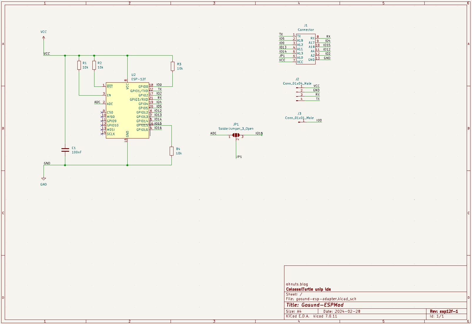
The schematic, other that the change of ESP module footprint, is pretty much the same.
And after ordering a few of these boards in the appropriate 0.8mm thickness, I was quite happy to see that at the very least it fitted, and the pins were not only aligned correctly but also in a number matching the module being replaced. Good times :)
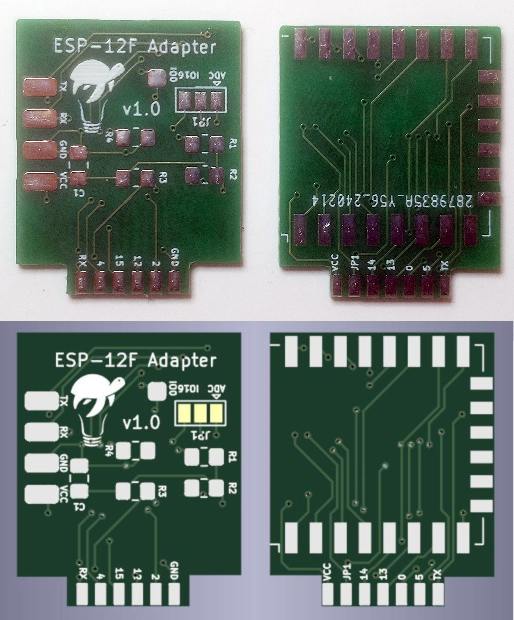
And that's it for the hardware, I've got it assembled and ready to test!
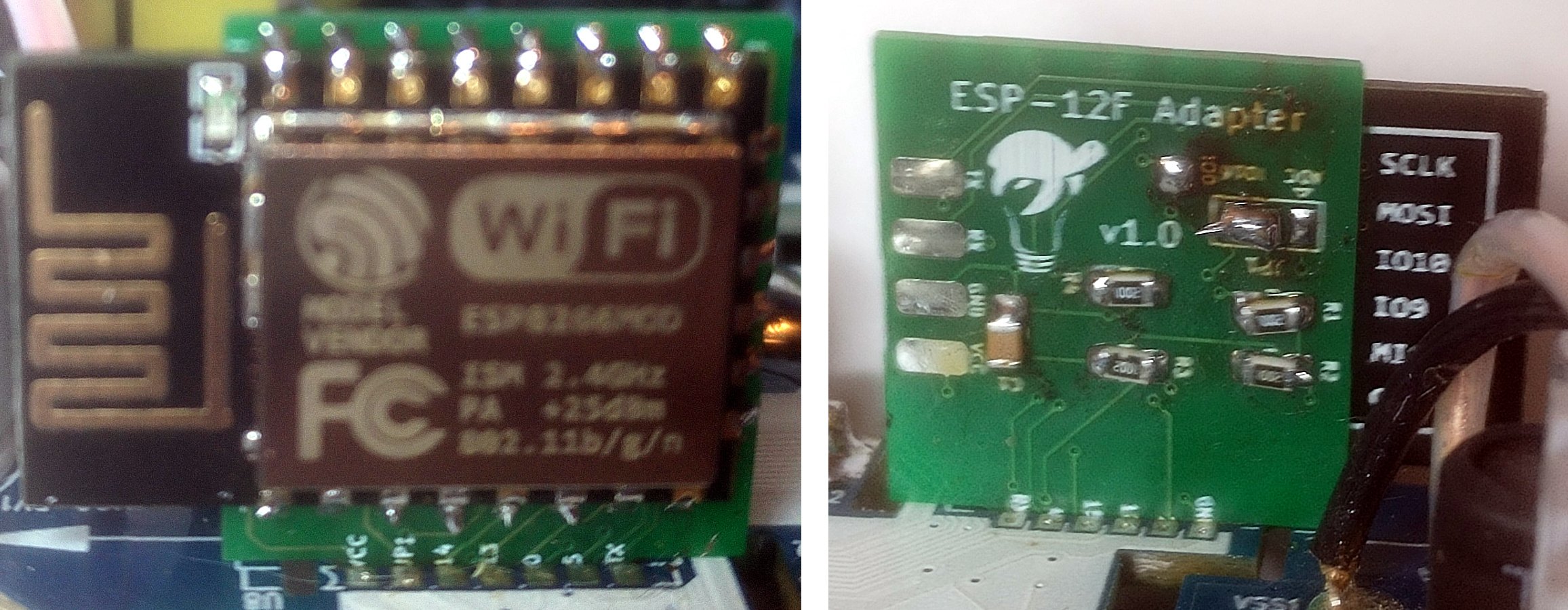
Sorry for the horrible focus
You can find the modified adapter schematic on github and I'll be sure to open a pull request on Chris' repository, just in case he wants to merge this in for some reason.
And now for the firmware side
So while still having the 5 pin header soldered and no mains connection, or in other words the PCB completely detached from the case and power pins, I wanted to try uploading something, I'm not really sure at this point everything is well connected, let alone actually working.
Deciding on which firmware to start with, the references I had already used all pointed to Tasmota but I really want to do ESPHome, as although I have an MQTT server set up I love the direct integration that ESPHome affords for Home Assistant. So, looking at the what references I have collected so far on this, there are two Tasmota configurations;
{"NAME":"Gosund 112v3.4","GPIO":[56,0,57,0,132,134,0,0,131,30,21,0,0],"FLAG":4,"BASE":18}
And one from the Gosund-ESPMod github repository I used as a base for the adapter:
{"NAME":"Gosund SP112 ESP-M2","GPIO":[288,0,289,0,2656,2720,0,0,2624,257,224,0,32,0],"FLAG":0,"BASE":18}
These are not even close, though... but that's actually correct because according to Tasmota docs from version 9.1 on the pin numbering changed, and along with it came the deprecation of the FLAG entry too.
Starting there, with the FLAG, which was 4 pre Tasmota 9.1, meaning we're using IO16 as a digital input (button), and not A0 which is the single ADC port in the ESP8285/8266 modules. If you look at the schematic for the adapter you'll find that JP1 on the adapter pinout will be shorted to either ADC or IO16 on the ESP side, so I guess this flag will help Tasmota know how to use that particular pin.
On the post 9.1 version FLAG has no meaning, but both IO16 and IO17/A0 are configured in the GPIO section (there's one added entry to that list).
The docs explain the GPIO field as
Numbers from 0 to 65535 representing GPIO0 to GPIO5, GPIO09, GPIO10 and GPIO12 to GPIO16 and GPIO17 for A0 pin for ESP8266. ESP32 has more configurable GPIO's
and parsing that into a table we get something like:
| ESP GPIO | Old GPIO | Old Name | New GPIO | New Name |
|---|---|---|---|---|
| 14 | 21 | Relay1 | 224 | Relay1 |
| 13 | 30 | Relay2i | 257 | Relay_i2 |
| 0 | 56 | Led1i | ||
| 2 | 57 | Led2i | ||
| 0 | 288 | Led1 | ||
| 2 | 289 | Led2 | ||
| 12 | 131 | HLWBL SELi | 2624 | HLWBL SEL_i |
| 4 | 132 | HLWBL CF1 | 2656 | HLWBL CF1 |
| 5 | 134 | BL0937 CF | 2720 | BL0937 CF |
| 16 | FLAG | Button | 32 | Button1 |
And this gives us a good preliminary mapping of IOs to functions, now we need to make this an ESPHome configuration file, and rather than start from scratch I searched for something close to what we're aiming for and this config file for a previous version of the plug seemed pretty much as perfect as we'd get, though to be honest I stopped my search at this first positive hit.
So, using that template and my table above, I crossed my finger, shorted IO0 to ground and ran esphome run with that file:
$ esphome run gosund_sp111.yaml

INFO ESPHome 2024.2.1
INFO Reading configuration .\gosund_sp111.yaml...
WARNING 'esp_plug': Using the '_' (underscore) character in the hostname is discouraged as it can cause problems with some DHCP and local name services. For more information, see https://esphome.io/guides/faq.html#why-shouldn-t-i-use-underscores-in-my-device-name
INFO Detected timezone 'Europe/London'
INFO Generating C++ source...
INFO Compiling app...
Processing esp_plug (board: esp8285; framework: arduino; platform: platformio/espressif8266@3.2.0)

--8<--

Building in release mode
Retrieving maximum program size .pioenvs\esp_plug\firmware.elf
Checking size .pioenvs\esp_plug\firmware.elf
Advanced Memory Usage is available via "PlatformIO Home > Project Inspect"
RAM: [==== ] 41.4% (used 33928 bytes from 81920 bytes)
Flash: [==== ] 43.0% (used 440381 bytes from 1023984 bytes)
============================================= [SUCCESS] Took 1.66 seconds =============================================
INFO Successfully compiled program.

--8<---

Connecting....
Chip is ESP8266EX
Features: WiFi
Crystal is 26MHz
MAC: 84:f3:eb:b4:82:48
Uploading stub...
Running stub...
Stub running...
Changing baud rate to 460800
Changed.
Configuring flash size...
Auto-detected Flash size: 4MB
Flash will be erased from 0x00000000 to 0x0006cfff...
Flash params set to 0x0340
Compressed 444528 bytes to 308222...
Wrote 444528 bytes (308222 compressed) at 0x00000000 in 7.1 seconds (effective 500.3 kbit/s)...
Hash of data verified.

Leaving...
Hard resetting via RTS pin...
INFO Successfully uploaded program.

--8<--

[21:32:51][D][wifi:474]: Found networks:
Woot! worked first time around :) So now that we have something we can update over the air, I need to resolder the PCB to the plug pins and assemble everything to make is safe(r) to operate connected to mains voltage.
Fine tuning and a bit of karma
Running that initial testing I find that the GPIO pins are slightly off, so I remapped them to match what I am seeing:
| ESP GPIO | Name | Actual function |
|---|---|---|
| 0 | Led1 | inverted led red |
| 4 | HLWBL CF1 | correct |
| 5 | BL0937 CF | correct |
| 12 | HLWBL SEL_i | correct |
| 13 | Relay_i2 | inverted usb power relay |
| 14 | Relay1 | Mains power relay |
| 15 | inverted led blue | |
| 2 | Led2 | |
| 16 | Button1 |
And here begins the karmic alignment hinted at the very start of this journey... I should have ran a more thorough test on this plug before starting to poke and probe at it, as I could not make the button share its state at all. Finally, and feeling like I exhausted all possible combinations of GPIOs and functions, I decided to put the multimeter to use, always with the plug disconnected from power, just to try and assert some logic into all this.
What I found leads me to believe I broke something along the way, or maybe it was broken to start with, we'll never know, but GPIO16 reads ~7 ohm to ground when unpressed, and pressing it drops the resistance to ~1.5 ohm, and there's about 1.6Kohm to VCC. This really doesn't feel like a healthy button circuit at all.
Unfortunately getting to the PCB traces to find and potentially fix the issue implies de-soldering the plug pins again and, lets be honest, I can live without a button :)
My final ESPHome configuration, still holding a hopeful button configuration:
# Gosund SP112 smart plug with power sensor

# Enable Web server
web_server:
  port: 80
#
substitutions:
  plug_name: wifiplug
  # Higher value gives lower watt readout
  current_res: "0.0012"
  # Lower value gives lower voltage readout
  voltage_div: "771"
#
esphome:
  name: ${plug_name}
  platform: ESP8266
  board: esp12e

# WiFi connection
wifi:
  networks:
  - ssid: "<redacted>"
    password: "<redacted>"

  # Optional manual IP
#  manual_ip:
#    static_ip: 172.20.10.8
#    gateway: 172.20.10.1
#    subnet: 255.255.255.0

  # Enable fallback hotspot (captive portal) in case wifi connection fails
  ap:
    ssid: "${plug_name}_AP"
    password: "${plug_name}"

captive_portal:


# Enable logging
logger:

# Enable Home Assistant API
api:

ota:

time:
  - platform: homeassistant
    id: homeassistant_time

binary_sensor:
  - platform: gpio
    pin:
      number: GPIO16
      inverted: false
    name: "${plug_name}_Button"
    on_press:
      - switch.toggle: mains_relay

switch:
- platform: gpio
  name: "${plug_name}_Mains_Relay"
  id: mains_relay
  pin: GPIO14
  restore_mode: ALWAYS_ON
- platform: gpio
  name: "${plug_name}_USB_Relay"
  pin: GPIO13
  inverted: true
  restore_mode: ALWAYS_ON
- platform: gpio
  name: "${plug_name}_LED_Blue"
  pin: GPIO15
  inverted: True
  restore_mode: ALWAYS_OFF
- platform: gpio
  name: "${plug_name}_LED_Red"
  pin: GPIO00
  inverted: True
  restore_mode: ALWAYS_OFF
sensor:
  - platform: hlw8012
    sel_pin:
      number: GPIO12
      inverted: True
    cf_pin: GPIO05
    cf1_pin: GPIO04
    current_resistor: ${current_res}
    voltage_divider: ${voltage_div}
    change_mode_every: 3
    update_interval: 5s
    current:
      name: "${plug_name}_Amperage"
      unit_of_measurement: A
      accuracy_decimals: 3
    voltage:
      name: "${plug_name}_Voltage"
      unit_of_measurement: V
      accuracy_decimals: 1
    power:
      name: "${plug_name}_Wattage"
      unit_of_measurement: W
      accuracy_decimals: 0
      filters:
      - multiply: 0.5
      id: "${plug_name}_Wattage"
  - platform: total_daily_energy
    name: "${plug_name}_Total Daily Energy"
    power_id: "${plug_name}_Wattage"
    filters:
        # Multiplication factor from W to kW is 0.001
        - multiply: 0.001
    unit_of_measurement: kWh

# Extra sensor to keep track of plug uptime
  - platform: uptime
    name: ${plug_name}_Uptime Sensor
You can also find this file on the git repository.
Time took its toll
The whole project took a long time, as you may have perceived from the subtle notes here and there... I bought the plug in August 2022, and the wrong modules a couple of months later, which then took a few long weeks to arrive, and then I kinda left everything collecting dust for over a year, it seems.
Which would be fine, except this particular model of the plug seems to have been discontinued, and I am completely unaware if the CUCO module is still a thing that is being used with current WiFi plugs. I will need to grab whichever current devices look the most similar and check. But that's for another day, maybe I'll actually go about it in less than 2 years, but then again maybe not, only time will tell :)
Post Scriptum
This entry's thumb image was generated using Adobe's Firefly and, well, it could be better but I'm feeling lazy. And this is how the machines take over, I guess...
The repository for the ESP12F adapter: https://github.com/nutsoh/Gosund-ESPMod which is based on Chris Klinger's work