Look ma, no mains
or, a simple battery and solar solution for remote sensors
Building blocks are fine
Yes, yes, I know, I'm always so adamant about reinventing the wheel at every opportunity, but it seems like there is a hard limit to the amount of time a day has, which, I know, it caught me completely off guard too!
So, sometimes, every now and then, I actually try and reuse things other people sold me so I don't have to worry about some part of a project, or at the very least I can delegate that to a future time. How mature of me.
Setting the stage
There are many, many situations where I need some sensor or actuator to be deployed where there is no mains power available, and it is fun designing things to be as thrifty with they power usage as possible, but using these ESP32 type microcontrollers will limit somewhat how power budget conscious your device can be.
There are tricks, there are other microcontrollers, but there is also a fair bit of sun around, so a rechargeable battery, solar charge circuit, some protection and a little bit of monitoring should allow for isolated sensors.
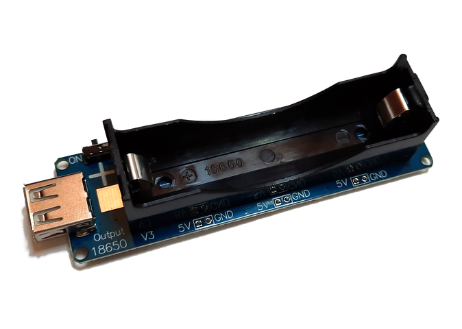
Or I can just buy one of these and reuse one of many 18650 LiIon batteries I have lying around...
Not ideal, but good enough
There's a lot of good stuff packed in this not so much larger than the cell holder board. It has 3.3V and 5V regulated outputs through pads you can solder pin headers to, it has a USB type A socket for power out and it charges using a separate micro USB socket.
Unlike all the dirt cheap 18650 cell based power banks I have tried before, this one does not turn itself off when it doesn't detect anything pulling power from its output, which will be a given not only due to the low, low power requirements of these devices I am designing, but also because I try to keep them deep sleeping as long as possible to conserve energy.
There's some cell protection included too, this is after all also a charger, and as far as I can measure it seems to charge at a consistent 500mA from empty, with a caveat I'll explain next, and will do that till close to fully charged, at which point it enters the constant voltage stage.
- Discharge cutoff: 2.50v
- Charge current: 500mA
- Charge cutoff: 4.15v
- Charge reconnect: 4.00v

Graph of battery voltage by time with a sensor. Sometime before noon on Oct 21 I turned off the power supply that was charging the battery.
But there's a weird behavior here, as hinted above; when the power is cut off at 2.5v, the charge current, when charging power is applied, is a conservative 60mA. Ok, fair enough, trickle charge an over discharged battery to avoid damage, fire and explosions, not necessarily in that order... but it does not appear to be sharing that power with the device connected through USB, nor are the 3.3V and 5V rails fully working, as they are both showing below 3V.
This would not be a problem if the charger was concentrating all the available charge (even if capped) to charge the battery to a sane level, and would power up the device once some voltage was reached, say 3V or thereabouts, and the charge current would then be set to its max of 500mA. Only that is not what I am seeing;
- Once the battery discharges to 2.5v, power is cut to the device
- Once 5V are applied to the charge port, charger starts pulling 60mA, slowly charging the battery up to some 2.9V
- It then stays there, probably trying to start the buck / boost controller(s) and that taking more than its fair share of the 60mA available. It is likely still charging, but I left it for 2 days and if anything the battery voltage went down.
I then disconnected the device and immediately the charge current jumped to 500mA, so... maybe it needs a power cycle. It's weird though, as this particular sensor deep sleeps for 1 minute, and then works for 10 seconds. It does have some current draw while in deep sleep, but under 1mA. I suppose that is enough to prevent the charger from changing to safe charge mode, or something along those lines.
So, being all scientific about it, I decided to allow the battery to drain and attempt a slightly different approach:
- Battery discharged to 2.5V, power cut off
- Apply 5V to charge port, 60mA being drawn, nothing on the device
- I toggle off and on the little output enable switch on the side of the charger
- The device is powered on, but charge current remains at 60mA
Well, that's something, it might now trickle charge to a set voltage and then remove the charge current cap, so I wait...
And I wait... After a good dozen hours de cell voltage holds steady at 2.74V, which is definitely not promissing, since 60mA x 12 = 720mA ~ 25% of the cell rated capacity, and the voltage / charge curve for these cells would put the expected voltage squarely on the flat part of the curve, above 3.3V.
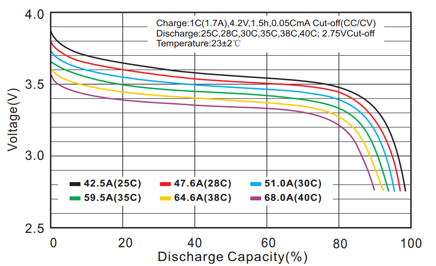
Shamelessly borrowed from Quora
Taking a few measurements and we have 2.18V on the charger's 3.3V rail, 3.19V on the 5V rail and 2.84 as seen on the USB connector. This feels like all the boost converters are taking the bulk of the available current, doesn't it?
Doing a quick flip of the USB power switch immediately gets the charger pulling 500mA, and stay that way with the board powered. So, yeah, I know I need to improve on the deep sleep mechanism (as it is not only the MCU that is pulling power) of that sensor board, but that a subject for a different post. Still, this only happens if the battery gets drained, so I guess for the time being that is "good enough™". This is not meant for a remote, hard to reach location anyway.
And the plan is...
I'm going to pair this with a small 5V solar panel. I need something like 100mA while running the sensor, that's for 10 seconds followed by 60 seconds of low power mode, which should be less than 1mA, but just to be safe lets call it 10mA.
Total power consumption over 1h will be 100mA/7 (or 10 seconds every 70) + 10mA ~= 14.29 + 10 ~= 25mA/h. So one day will be 24 times that, or 600mA. Assuming I get 4 good hours of sun every day, and around here it is usually much better than that on average, and I need to get myself a panel that provides a realistic 150mA peak at a bare minimum, or ~0.75W @ 5V. Also anything above 500mA, or 2.5W @ 5V, is likely falling in the diminishing returns side of the equation, even though a panel that can provide 5W at peak can provide 2.5W for lower irradiation, thus increasing the peak charge time per day, in theory. This is probably not a hard panel to source.
Best laid plans and all, it dawns on me that we should be getting just over 4 days of operation based on the 600mA per day figure above and the 2500mAh cell I am using, and yet I count something between 2 and 3 days based on the discharge graph above, which is a real run will the real sensor I'm going to use this with. It is a used cell, which while I did buy it new, has seen some deep discharges in its life so maybe its capacity has just degraded that much, so I tried a charge cycle using a dedicated charger, one of those that states how much current has been used to fill the battery. The one I have unfortunately does not do the discharge, which is where you can accurately measure capacity, but still this should give me a ballpark of the battery capacity.
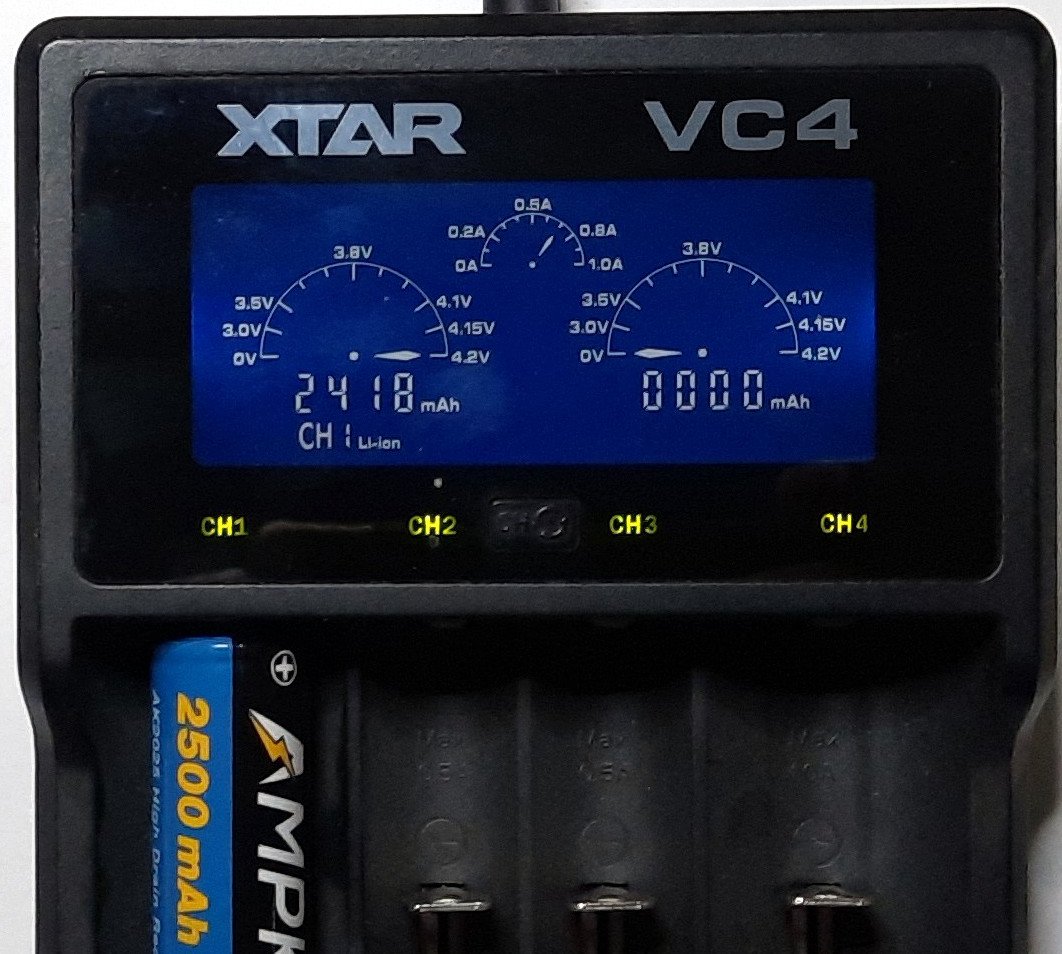
Fully charged to 4.2V, took 2418mAh
Close enough to 2500mAh, but there's another variable here, the dedicated charger got the cell up to 4.2V whereas the "power bank" we are testing only pushes it to 4.15V, which should still not account for anything particularly impressive (just refer to the discharge curve graph) but still, something else to keep in mind.
Still, with the 4.2V starting voltage the run time doesn't change, not surprising anyone. My best guess at this point is that the power profile of the sensor has many very short peaks and my bench power supply just doesn't have the resolution, ending up showing an average that is, well, below average. Or, of course, the roundtrip efficiency of the battery charger board when supplying the USB's 5V rail is horrendous, which is not something that would come as a surprise.
A proper power measurement is in order but I don't really have the equipment for it. So... 60 hours per charge should be plenty, assuming the battery gets recharged fast enough which will depend on the panel chosen and the whims of the sun.
Some caveats included
There were quite a few head scratching moments where the device just wouldn't power up until I would connect the battery with the output switch off and no load connected to it. Measuring the 5V and 3.3V rails would show something, but very low, around 1V.
I would still need to remove and reinsert the battery a few times before the thing would behave, which does not fill me with confidence. One such case was after I charged the battery to 4.2V externally, so maybe that is a factor, but my money is on a separate, not described above design decision I have been keeping to myself, or at least for the post about the sensor I used here with the battery; I assume that due to the buck/boost design of this thing, the battery negative is not connected to the ground reference for the 5V, 3.3V and USB rails, so in order to measure the battery voltage on the sensor I connect it directly to an opamp which I then use to feed the analog input that will measure the voltage. This, perhaps, introduces some potential shift on the ground that introduces problems with the 18650 power bank protection circuits. I was too lazy to redo all the testing without the voltage sensing attached, so this will, for the time being, remain a theory.