Low power water valve DIY
or, off grid irrigation automation

Setting the stage
There are many irrigation valves in the market, from big names as well as unbranded stuff, with prices ranging from "I can't believe how cheap this is" to "wut??". But it seems that most of them are designed with a proper installation in place, as in, you'll have a controller that will be connected to mains power, will drop the voltage with a transformer to something manageable, like 24v, maybe 48v, not so low that long wire resistance will drop the voltage beyond usefulness, and that's that.
I, however, have a slightly different approach in mind, and I'm sure that if I searched properly I would find a ready to use solution that would fit my needs, but I'm lazy, cheap and way too confident in my capabilities, so I'm going to try to hack something up myself, of course.
There are 2 reasons for not going with a common, mains powered solution. One is installation, I really don't want to be digging trenches and laying long stretches of cable, and the other is a side effect of that, as commonly these valves will have AC driven solenoids.
And there are DC solenoids, price is pretty much the same, in fact one can use DC on an AC solenoid, though care needs to be taken to avoid burning the coil from overcurrent. Anyway, that is not the rabbit hole I intend to jump down on, but rather, going back to the off-grid mindset, the sheer power required to hold the solenoid when the valve is in its non resting state...
And addressing the stage lights power usage
Looking at a basic valve with a 24v AC solenoid spec sheet, we're talking about an initial inrush current of 0.4A, along with a holding current of 0.1+A. I couldn't find specifications for an equivalent DC variant, but the theory states it will be less efficient overall, with a constant power drain somewhere above the holding current of the AC counterpart.
That's quite a lot. These power requirements taken as a snapshot mean very little, but lets add some more variables to this equation, shall we?
My water pressure is not the worst for home use, there's something near 1.5 bar (~22 PSI) from the tank and I have a constant pressure pump pushing 3 bar (~44 PSI) to the house. This is because there's a good drop between my main tank and the house, but for irrigation I have a few other tanks that collect rainwater and have a much lower head available, so maybe I can get close to 1 bar? This does work for watering the plants, I have been doing it manually after all, but I'll need to balance the number of things I water in parallel and the time I water them for, so if I could get 100 valves going in good coordination I could likely make every drop of water count, but that's not a reasonable goal, at least for now.
Alternatively, I can extend the watering outputs per line to as many as I can without losing all the water pressure, but I will need to run them for much longer.
Either way, this becomes a problem to do off grid, as even if I was to get 24v DC solenoids running at 0.1A/h, running 4 hours a day total, a pack of 8x18650 LiIon cells at 2Ah would net me 5 days of usage ignoring a lot of details like the controller and such, and that does not look too bad.
I can always charge the pack with a solar panel, I am in one of those places in the world that struggles with water shortages, not lack of sun. A 10W solar panel should do nicely, although I'll likely not find a low power solar panel in the 30V peak range, but we can step up the voltage or get larger panels.
Of course there's a small catch, that's one valve for 4 hours, maybe 4 valves for one hour each. I'm going to need more, if only for the more granular control of what is being watered, as I don't have a perfect square in my land that is littered with trees and herbs and flowers and allows for watering everything neatly in one place. And I'll need to water things for longer too, and more in parallel as there are multiple tanks for multiple areas allowing for independent water pressure zones.
Just the sheer cost of the power storage and charging would make this a no-go, honestly, even before considering the price of the valves themselves.
Something less "professional"
I had used them in the past, these programmable garden valves that operate for a long, long time using a couple of AA batteries, and so I went to my local home improvement store to try and find some. And find I did, there were a few choices, some with digital configuration but I'm pretty sure the easiest to hack will be the ones with a rotary knob, such that I can simulate that knob to control the valve, and it just turns out these are actually the cheapest option around, so score! And taking the reported specs on the blister seriously, this thing handles 0 to 8 bars (~116 PSI) of water pressure, plenty enough and then some.
I got 3 of them, so I could toil away without fear of destroying stuff in the process, and proceeded to open one up.
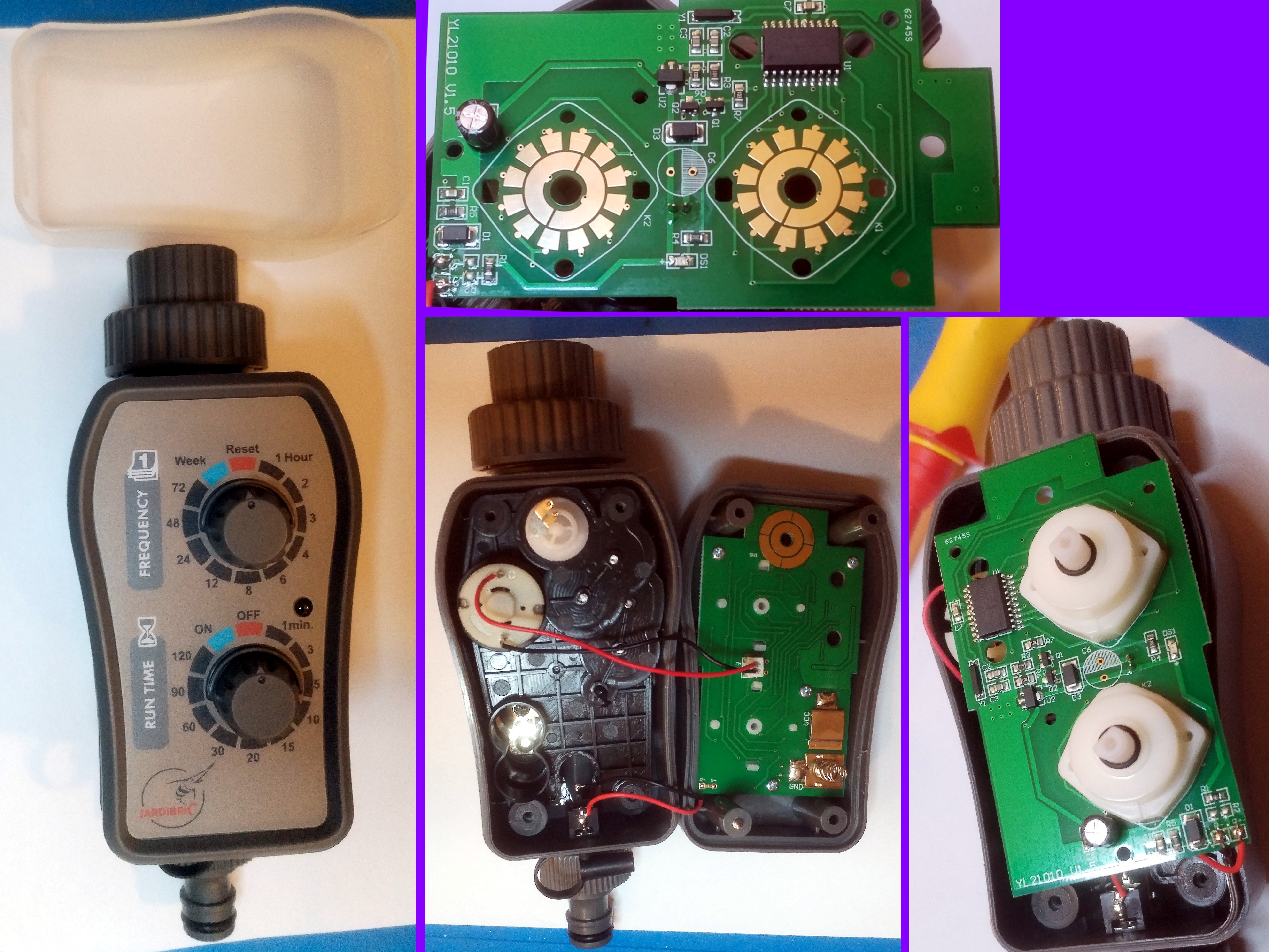
The valve, in various states of desconstruction
Mechanically, this simple device has a ball valve connected to a wee motor with some basic position sensing, that's visible on the bottom middle image, the round thing at the top of it. There are obviously so gearing down of the motor rotation, as one would expect.
The controller chip is some general use 8 bit thingy, for which you can check the datasheet at the manufacturer's website and a little probing around shows that the rocker switches are arranged in a 6x4 grid of I/O pins, as per this image:
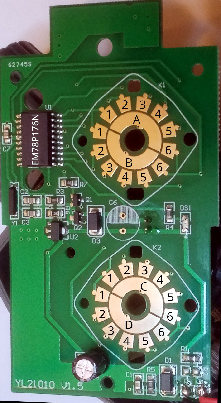
Detail of the PCB showing pads and my numbering of them
Looking at the contacts on the bottom switch and I can see that OFF is C6 and ON is C5. I don't really care about any other combination, honestly.
Basics time, I assert the valve operates without any of the rocker switches, or in other words, with all control paths disconnected, which is never the case when used as designed. This isn't strictly necessary, but knowing this now will prevent me chasing wild geese later when hacking begins.
It does, and while I have the thing connected and the control pads bare, I short C5 and the valve opens, nice! Leaving it shorted behaves in the obvious way, nothing happens, and opening C5 but not shorting anything else seems to stay in the open position, which is great. Shorting C6 closes the valve and we're golden.
And the hacking begins
First attempt at external control was to Frankenstein a relay onto the contacts that were being shorted in positions off and on. This worked really well, but the relay will pull more power (around 0.12A) than the motor spinning (some 0.08A) at 3v, so... lets see exactly what is going on with these switches, understand how the microcontroller is checking their state.
Probing with my handheld oscilloscope, because I'm too lazy to grab the big one, I check what happens between ground and point C:
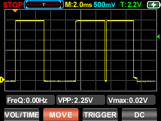
Pad C capture
Never mind the figures presented by the scope, the fact I moved the waveform to make it pretty for the photo must have really confused the poor fellow. Knowing the trigger (little green arrow on the right) is at 2.2v as advertised, and having 500mv per division means the base line is ground, and VPP is 3v, which incidentally is exactly what I'm powering the whole contraption with.
This happens every 4 seconds, 3 positive pulses of ~4ms each, with one full 4ms space between the first and second, and a negligeable space between the second and third.
While the "complex" signal should prevent me from simply feeding 3v to the appropriate input, at least in theory, I could always just use a pair of MOSFETs to act as the switch. In fact, with one of the MOSFETs set up as a digital inverter I could actually use a single control signal to open and close the valve, just like with the relay.
And yes, I did feed VCC to pad 5 but that was never going to work if I had just though 2 seconds about it ahead of actually doing it... even if the microcontroller wasn't checking the sent signal as depicted above and just checking for a positive "pulse", I would be feeding 4 inputs with it: run now, run every 8 hours, stay on, turn on for 15 minutes. And even if somehow all that added up to something the microcontroller could discern as "turn on, right?", turning off would then be even more confusing.
In the end the inputs are sinking too much current anyway, so when connecting pad 5 to VCC it was dumping 50mA, which is not ideal, if not actually damaging in the long run.
FET time
I tried a simple 2 signal MOSFET approach, using what I had around which were BS170 https://www.farnell.com/datasheets/1571864.pdf. There is one control switch for both gates in parallel, then one MOSFET drives pad 5 and the other shorts to ground. The former has the drain connected to pad C, the other has a pullup to pad C and drives pad 6.
The theory is, if the MOSFETs are off and there's a positive pulse in pad C, pad 6 is high, pad 5 is low, if they are on, it's the opposite way. Something like this:
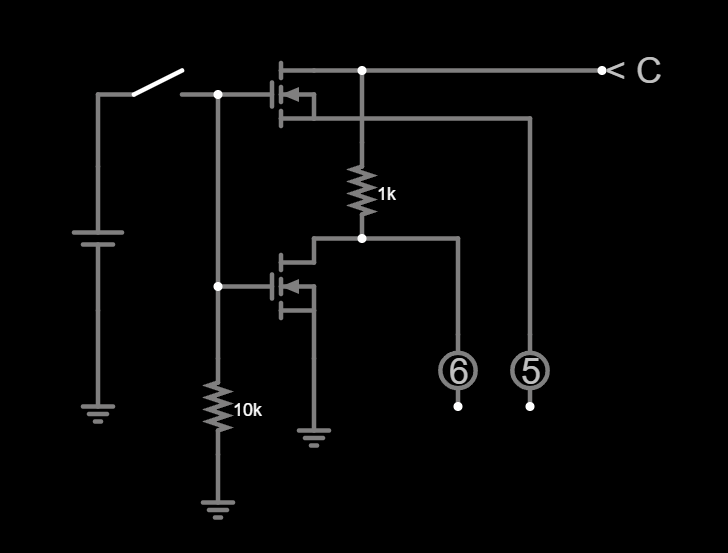
two MOSFET switches, outputs are inverted between each other
At first sight, this appeared to be working; starting from a closed valve state I turned the MOSFETs on by driving the gate high and the valve opened. This was about to become a short one, he thought...
But then driving the MOSFET gate low did nothing... I restarted, MOSFET off, manually short pads C and 6 and nothing, the valve does not close. Well that's weird, so I decide to take my lazy ass off the chair for a second to grab the logic analyzer, remove the pad connections from the circuit and probe them, channel 0 is pad C, 1 is pad 6 and 2 is pad 5
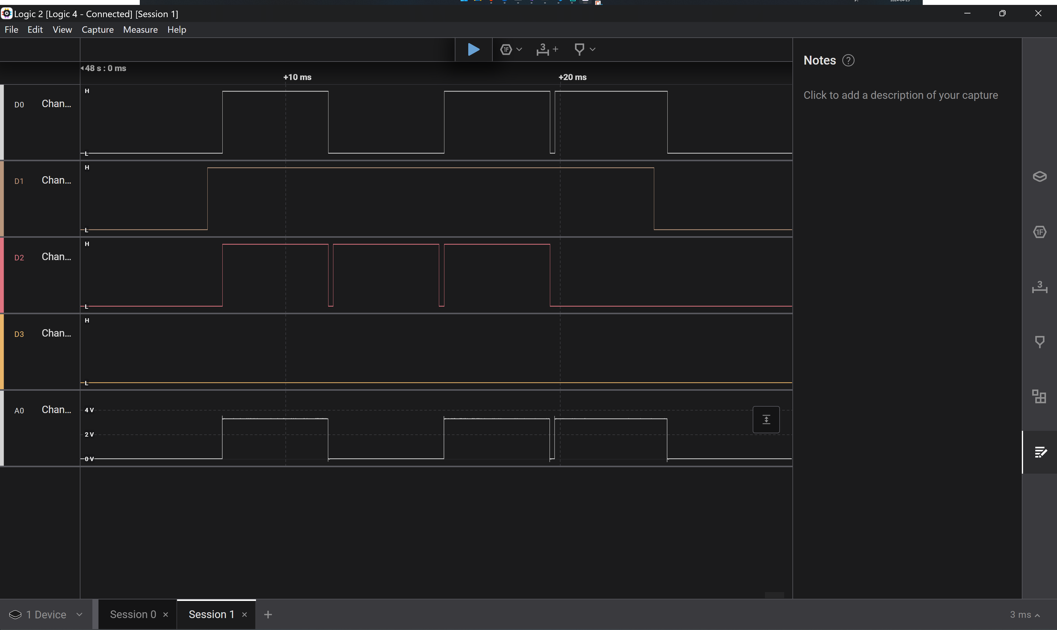
Logic Analyzer: All pads open
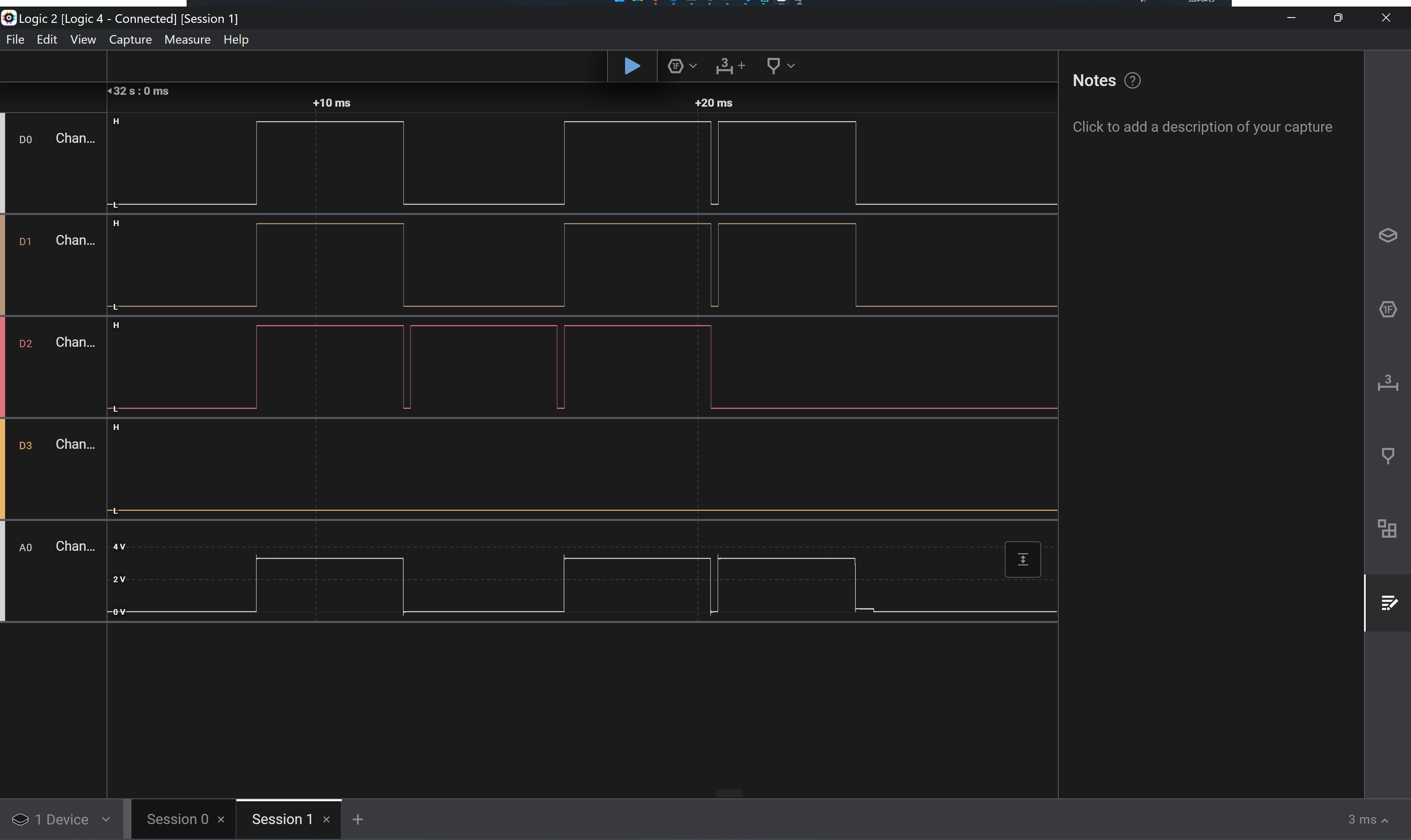
Logic Analyzer: Shorting pads C and 6
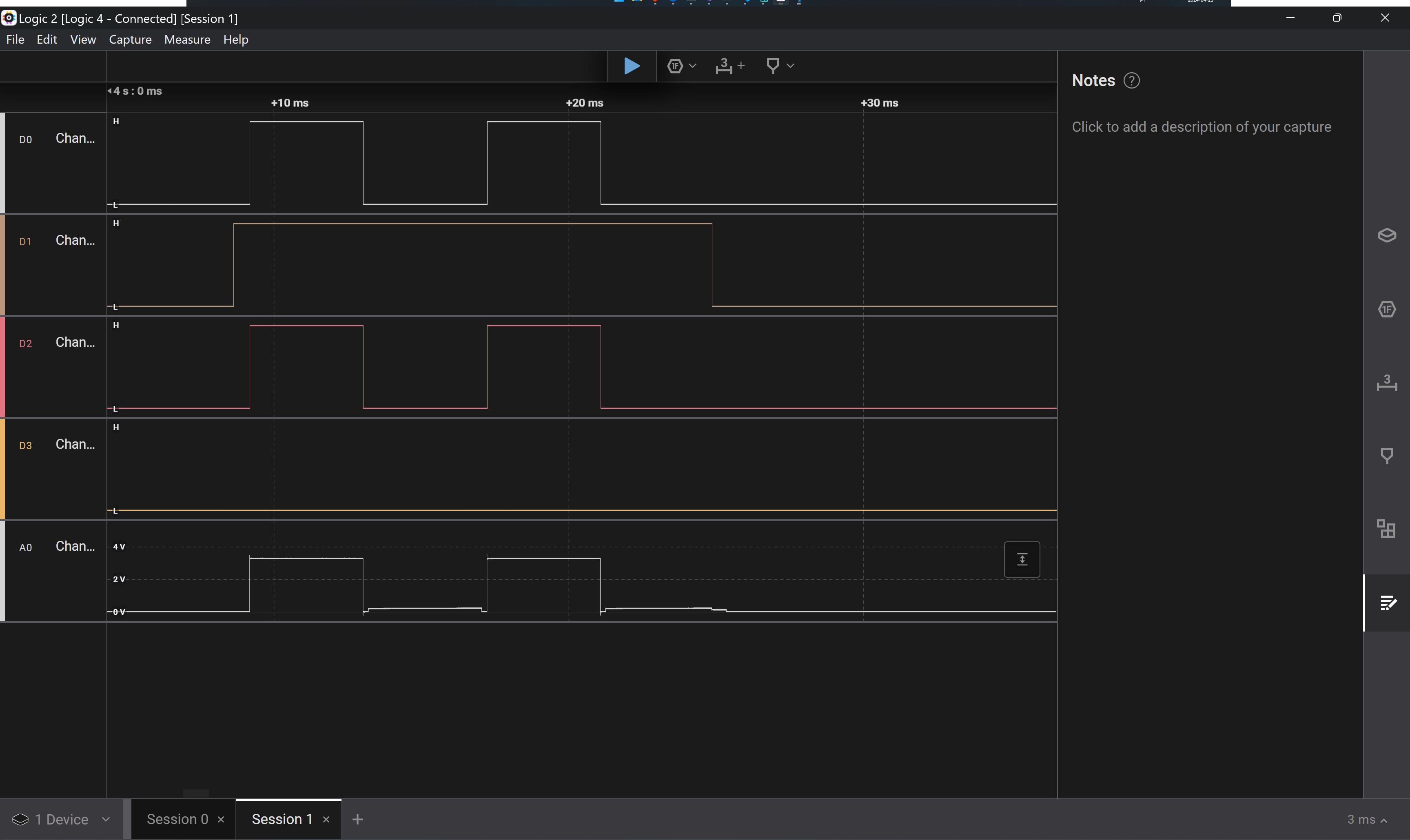
Logic Analyzer: Shorting pads C and 5
Looking at this, it was apparent why my initial MOSFET approach failed to work, as logic levels are "inverted", the high state is the default, likely with a fairly weak pullup, and the low state is what is being actively driven.
This makes perfect sense for the use case, an open collector output on each numbered pad will allow for a low state pad C to override pull the line low, and not sink whatever current is available between pads.
Channel 1 above shows 4 high bits, but if it had been shorted to pad C, it would follow the dips, i.e. it would read 1, 0, 1, 0. But why is channel 2 set to 1, 1, 1, 0? That would make it lose one potential bit of information? Is this reading 2 bits of a letter pad, and 2 of a number pad?
Long story short, this made no sense, so I decided to probe everything, which told me a different story. One that actually makes sense, as now each letter pad is driven low at a different single bit, and all number pads are constantly high, i.e.:
| PAD | ||||
|---|---|---|---|---|
| A | H | H | H | L |
| B | H | H | L | H |
| C | H | L | H | H |
| D | L | H | H | H |
| # | H | H | H | H |
With this the implementation is much, much clearer. All pins connected to number pads are driven as inputs with a pull up, all letter pads are driven as outputs following the set serial bit data as per the table.
Knowing that there can be two separate shorts between letters and numbers, as there are two separate physical switches, it becomes easy to assert the rotary switches' state. So why did I not see this in the first place?
Well, because I assumed, and nothing good comes out of assumptions... I assumed I had removed both switches as shown in the photos, but there was some magic editing going on, I actually used two of the three units I got, one for photos and reverse engineering, one for the physical tests described above, but I only took the top switch out just now, as I was preparing to probe all pads. And even then it didn't register in my brain that I had been doing this wrong, only when I got different results for pad 6 (which was obviously shorted to pad A by the top switch) I realized the foolishness of my ways, oh well.
Back on track, now.
Still FET time, only upside down
What am I trying to achieve here, anyway? There are two inputs and I need to "short" either one or the other with output pad C to open or close the valve, and to do this with a single control line, i.e. if voltage is supplied to that line the valve opens, if not (hi-Z or GND) the valve closes.
So the truth table we're attempting to reproduce is:
| CTRL | Pad C | Pad 5 | Pad 6 |
|---|---|---|---|
| L | L | x | D |
| L | H | x | x |
| H | L | D | x |
| H | H | x | x |
L is Low, H is High, D is pulled down, X is untouched or Hi-Z
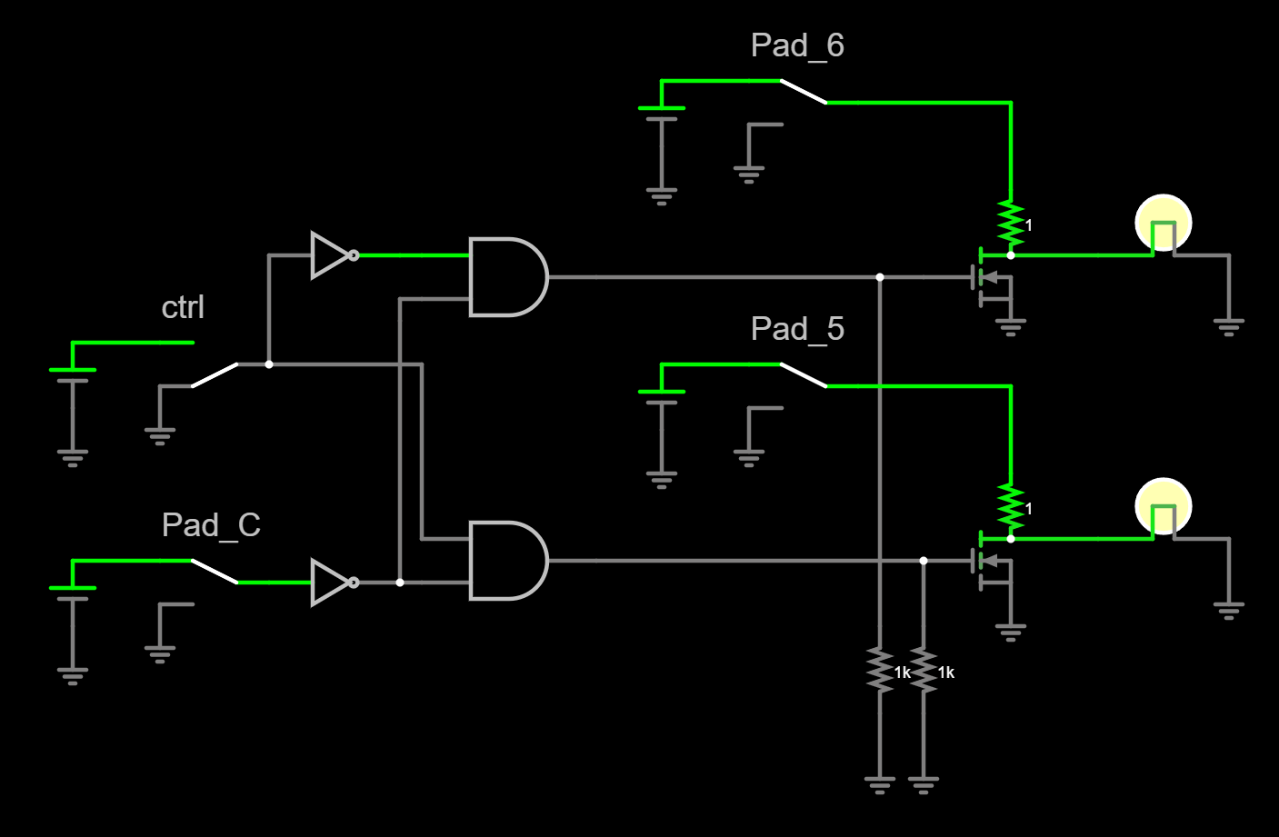
Using only N channel MOSFETs I can do this, in theory at least, with 4 of them, 1 for inverting the Pad C signal so we can then use 2 to do the number pad pull down, and one more to "invert" the ctrl signal so we can inhibit either one of the pull down MOSFETs depending on that.
The end result would be something like this:
4 N channel MOSFETs simulation
And moving the above plan to a breadboard did in fact provide me with the expected results, albeit after much troubleshooting of slight wiring mistakes and the usual bad breadboard connections:
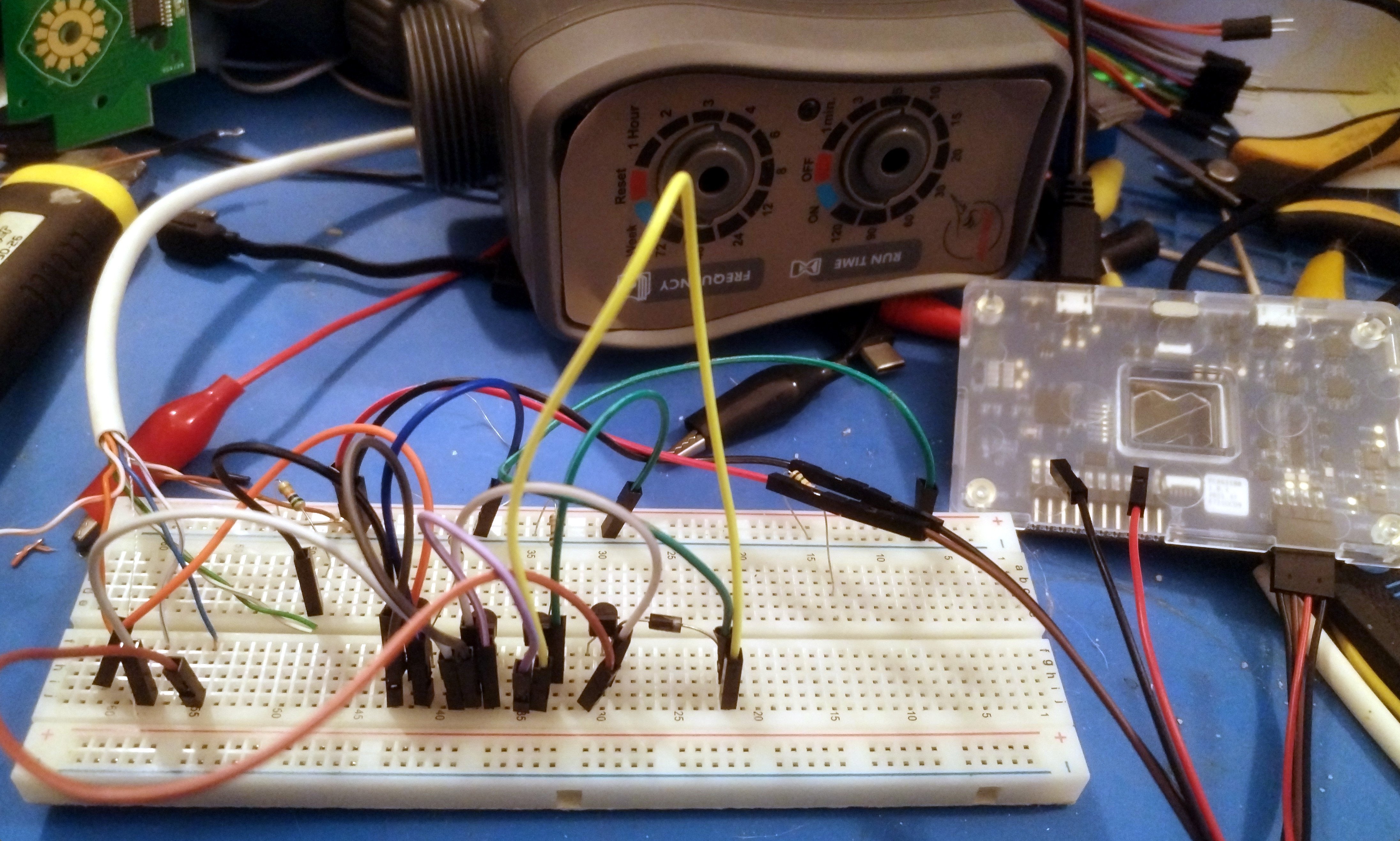
I'm no Ben Eater but.. yeah, I'm just not
You might notice the little gadget on the right side of the above picture, that's the Nordic Power Profiler Kit II, and it is awesome for any project that will require running from batteries. We'll talk more about the power sampling done later on, I promise.
Using a couple of P channel MOSFETs would avoid the use of the 1 N channel for the inverter:

2 P channel MOSFETs, 1 N channel MOSFET simulation
This is, once again, the theory. In practice I failed miserably to get this one working on the breadboard. You see, these simulations have a bulb to emulate the presence of VCC on the numbered pad, and when the pad is high but the MOSFETs are pulling it to GND, the resulting power draw from that "short" will bring that signal to GND, making the 0v space of the C pad take precedence. However, when simulating with LEDs I can never really pull the voltage down, it just sucks all the amps, so I had to use something the is power controlled, not voltage. This is just a side effect of the simulation, not exactly how it is in the real world, of course.
So, because of this, I failed to notice that the P channel FETs don't really "short" the source to drain properly, at least not for the voltages I am operating with and the specific MOSFET I'm using (TP0606), but doing a separate simulation with just the MOSFET and the power supply, in both N and P channel flavors, I can pull the high side (so my numbered pad) to GND via a 1 ohm resistor with the gate set to whatever is required to get the FET into saturation, and I end up with a few millivolts to drop on the N channel one, which is what I reproduced above, but with the P channel I get about 1.5v, matching what I saw on the breadboard. Why that is I do not know, I'll try to find out, but I do know from playing with power MOSFETs in the past that the static drain/source resistance of the P channels is usually higher, and I'm sure there are other differences that I'm just ignorant of.

Simulation of Nch and Pch MOSFET switching
For now? Lets skip this one, shall we?
And while I have zero experience with hardware logic gates, I do believe I can drive MOSFETs from their outputs, provided I make sure all voltage ranges match, since MOSFETs are voltage, and not current, driven. I will take this opportunity to experiment a bit, and I did do the simulation:
2 N channel MOSFETs, 2 AND gates, 2 inverters simulation
There's really no advantage that I can see in using this latter one, as the logic chips will be more expensive and I still need the two MOSFETs to pull the inputs to ground. I might be able to use the AND gates as sinks when their outputs are at FALSE state, not sure, which would at least make for the simplest version to route, but with all the internal buffering happening I don't think that'll be the case. Only one way to find out, I guess:
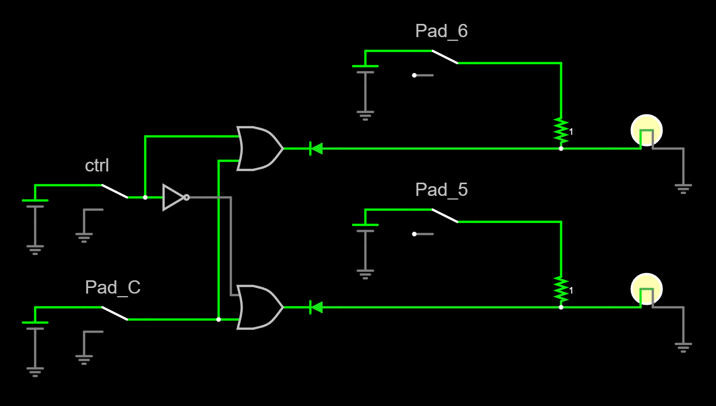
2 OR gates, 1 inverted simulation
Sipping power, pun intended
Let us finally address the power profile of all this. Well, all this I can test right now at least.
Using the 4 N channel MOSFETS approach on the breadboard and the Power Profiler, I looked at the opening and closing of the valve as well as the idle power in both open and closed states.
Starting with the motor draw on opening and closing:

Profiling opening (top) and closing (bottom) the valve
I know, the framing could have been so much better, but this is how I screen captured it, so this is what we have to work with :)
The results are, as very much expected, almost the same opening and closing the valve, as the motor always spins in the same direction and for the same time, it just turns 90º and that is it. And even though the capture time is much, much larger than what is spent with the motor spin itself, making the window average worthless, the graph itself matches neatly what I was seeing in my bench PSU, which was ~80mA for the motor. The 450mA peak also present no challenge here.
The motor spins for 7 seconds in each of these capture, voltage is 3V, that would be about 150uA/h consumed. Looking at the charge figure of ~460mC, at 3V that would be 383uA/h, or more than double that... maybe that's the result of the initial peak, maybe the 80mA is slightly offset, but regardless, lets run with the larger of the two and round it up, as all calculations should be done for worst case scenario, right?
Every time the motor spins, so every time we open or close the valve there's a 400uA/h requirement. I need to address now that I know this figure will likely change when testing is done under water pressure, but we'll cross that bridge when we get there.
Next is idle consumption:

Here both states show only a tiny amount of power draw, but that tiny amount is an order of magnitude higher on the open valve state, so why is that?
When the valve is open, we have the control line high, which is feeding VCC to the inverter MOSFET gate with a pull down resistor, and I cannot remember now, but if I did use a 15K resistor in the breadboard like stated in the simulation screenshot, that would definitely explain that. The pull down is actually not needed, as the gate is connected to the control line which should never be left floating, it is either VCC or GND, so we will likely achieve a similar power draw to that of the closed valve state in the end.
And for the worst case again, the 13mC of charge required, that amounts to 11uA/h.
There is a LOT missing here, the controller and DC/DC converters that will definitely be required if operating from rechargeable batteries, cable losses and oh so much more, but running with the figures we have, lets entertain a bogus scenario here, a parallel from the solenoid one presented at the very beginning of this write-up.
Assume we have one valve, runs once per day for 4 hours, and we have a pack of 8x18650 LiIon cells at 2Ah each, only not in series as required for the solenoid, but in parallel for ~3V, which gives us 16Ah of charge available.
Under this setup the solenoid gave us a 5 day runtime, lets run the numbers for the water valve:
We will open and close the valve once per day, leave it open for 4 hours. Since open or close, the idle power we are working with is the same, 11uA/h, we'll just do that times 24 hours (well, minus 14 seconds of valve travel, but even I am not that pedantic). That is 264uA per day.
On top we need 400uA/h each valve state, so 800uA per day.
Grand total is 1064uA per day. Lets double that and run with a round number of 2mA per day, or an average of 83uA/h, which we divide our total available charge by to come to 16Ah divided by 0.000083Ah or 192771 hours of runtime, which roughly equates to 8032 days, more than 22 years.
Slightly better than 5 days, I guess. Of course this is all just fun and games, these bench figures mean very little, and the idea would not be to provide 22 years of battery life to each valve, but if we could do 2 years on a battery or two, I could forego the solar charging completely and just change packs once a year.
This will likely not be that easy as the controlling system will be talking to my home automation through a wireless system of some description and that is probably taking some good power to keep running, but that is for another day.
I'll order some parts, get some PCBs made and we shall return to this project at a later date, as summer is coming and the trees, like ourselves, need to stay hydrated.
Drink plenty of water, people!
Post Scriptum
I think the robot overlords finally perfected A.I. to the point where it can take over human dependency on jobs where specific humans struggle, like for example coming up with rodent based blog entry images... so it begins!
All the simulations were run and screen captured from the amazing Circuit emulator at https://www.falstad.com/circuit/, specifically I used the full screen version thereof.
You can find the simulations as text files that you can import on this project's github repository, where assets from this and future entries in this series will be deposited