Solar EVSE - Proximity Pilot Edition
or, trying to slow things down

Setting the stage
I drive a hybrid vehicle. To charge it at home I use an old EVSE, which while not a charger it is what most people usually call it. You can also call it a charging station. I guess a rose by any other name...
It is a simple(ish) device that switches on and off mains to the car's (actual) charger, while also providing it with a control signal stating the max power it is allowed to pull and adding a bunch of safety features. Specifically, I have an IEC 62196.2 Type 2 connector Level 2 single phase 32A EVSE. Yep, I said it, now lets just move on, shall we?
My car charges at a maximum of 16A, and available to me are 2 cables, one single phase rated for 16A that was provided with the car, and another one, 3 phase 20 Amp that I bought with the sole purpose of doing some light hacking. You see, in my house there is a large enough solar installation to, when the sun shines just right, charge the car and support most loads for the car without needing to pull anything from the grid, which is great both for the environment and, well, my bank account doesn't complain either. But of course the sun does not always shines just right, and there are some large if occasional loads that need to be catered for as well, so ideally there should be be some control the charge rate all the way from the peak 16A to 0 based upon availability of solar energy and, of course, expected use of the car.
And this is actually a very easy thing to solve by throwing money at the problem. Honestly, not even that much money, but... eh, you know, that is just not how reality presents itself around here. I strive to be able to do all of this by adapting what I already have, so lets start by getting a problem statement down;
Ideally we want to be able to:
- Defer charging to when the sun is shining and there is enough production surplus
- Allow for charging current modulation to prevent pulling from the grid even if the full 16A aren't available from local generation
- Be able to pause charging and restart it as needed
The quick and dirty plan
Reading about the variables around electric car charging I see a bunch of references to the IEC 61851 standard, although I never got to see the actual text for it as apparently that is not a cheap document to download, the next best thing is the huge repository or tidbits from it repeated ad nauseum throughout the interwebs. Specifically, the Proximity Pilot is of particular interest as it is, in the case of Mode 3 charging, the tethered EVSE with a socket for a cable, the means by which said EVSE will assert the current carrying capability of the attached cable and will, in theory, inform the EV through the Control Pilot about the maximum amperage that the car can safely pull.
The Control Pilot (CP) is obviously the proper way to do what we need, but that involves hacking the EVSE proper, build my own or buy one that allows remote controlling. For this first attempt I'm going to try and do this based solely on the cable, so how does the Proximity Pilot (PP) work, then?
It is a fixed resistance between it and the Protective Earth (PE) on the EVSE side of the cable, which lets the latter know how much current the cable is rated for, as in:
| Resistor (Ω) | R range | I Max (A) |
|---|---|---|
| > 1500 | 6 | |
| 1500 | 1000 ... 2700 | 13 |
| 680 | 330 ... 1000 | 20 |
| 220 | 150 ... 330 | 32 |
| 100 | 50 ... 150 | 63 |
| < 100 | 80 |
So, I took apart the male side of my sacrificial cable, and low and behold a 680Ω resistor on a small PCB!
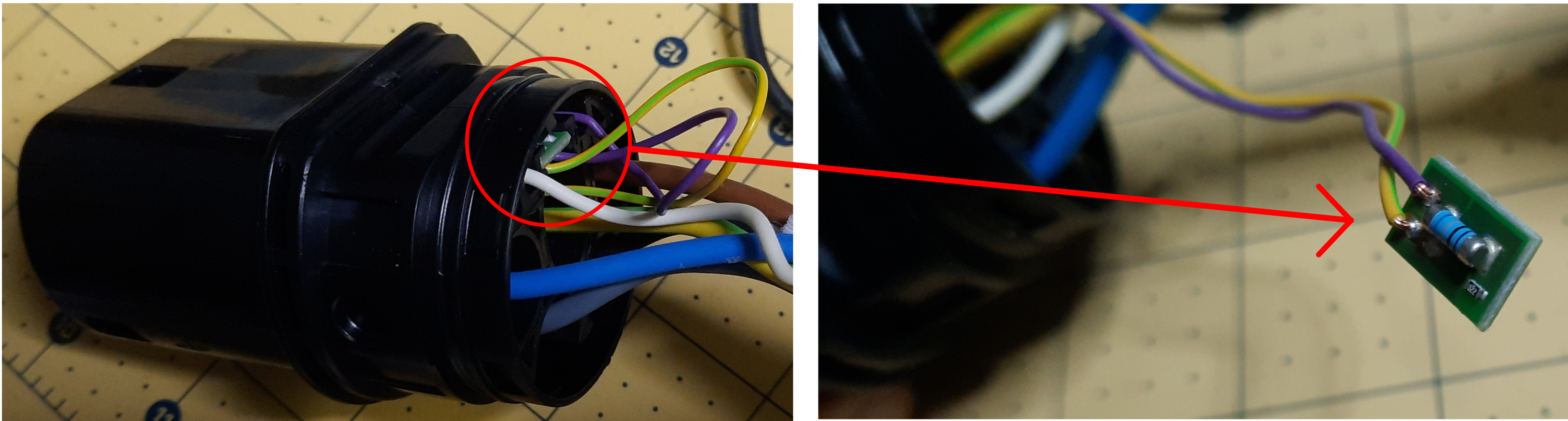
Can you spot the tiny 22Ω surface mount resistor there? It is not connected to anything
Now, that resistor has a couple of longish wires attached to the appropriate plug pins, so I'm going to remove it and add my own board. The idea here is to test if changing the resistors while charging elicits a change in charge current from the EVSE signal or, at the very least, if connecting the cable with a different resistor triggers a different limit advertised by the EVSE, as per the table above.
So I designed a small experiment with 3 resistors and 3 jumpers, which allows for the PP to be disconnected (meaning no cable), connected with 730Ω (20A), 1.4kΩ (13A) and 3.9kΩ (6A). These values were chosen because, well, those were the resistors I had available to me immediately.
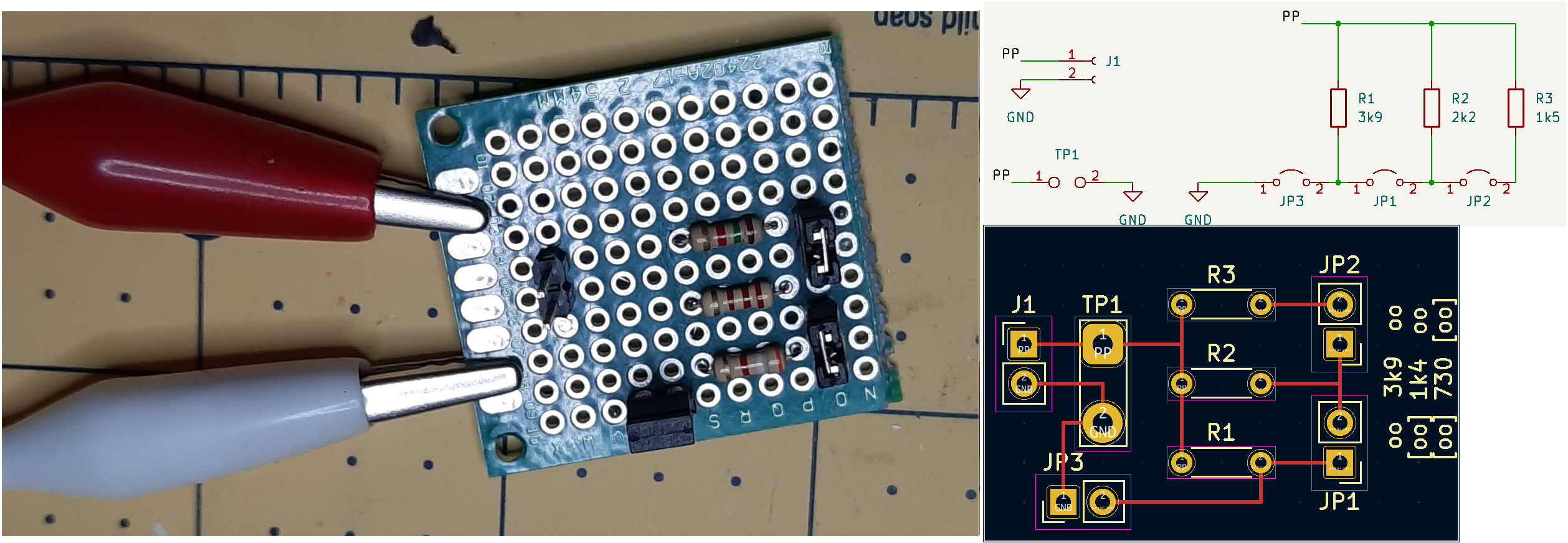
The testing board ready for attaching to the plug
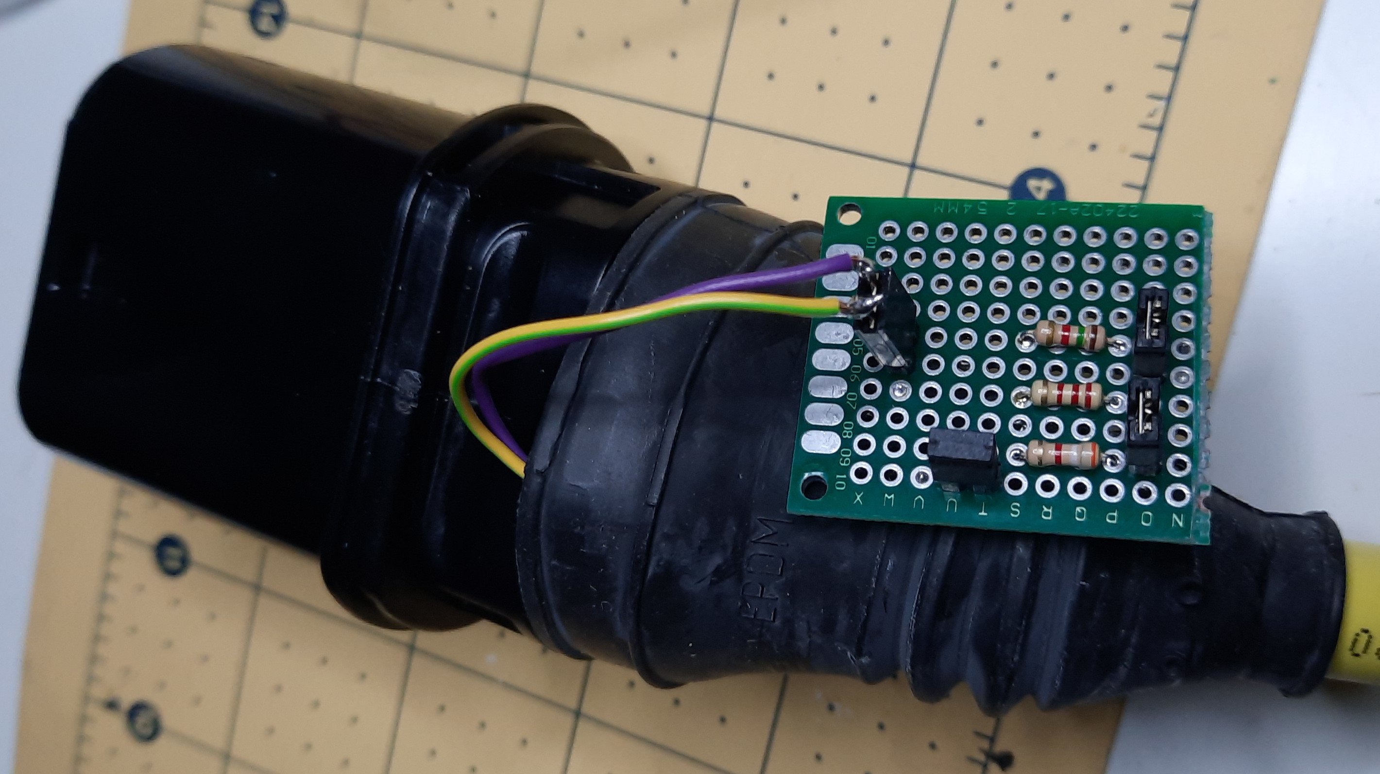
Soldering a connector to the now loose cables from the plug where the resistor PCB was, and rolling the protective sleeve over the assembly (I'm bold, but I like to think not that stupid!) just leaving the new board on the outside and we were ready for some tests!
First thing I tried was to, having JP1 and JP2 closed for 730Ω, but having JP3 open which completely disconnects PP from PE, connect the cable to the car and EVSE and... nothing happened, so first success! The absence of the PP connection to PE does prevent the EVSE from detecting the cable.
Next up, I closed JP3, and yep, click, click, click, the car starts charging at 16A, as expected.
Opening JP3 immediately stops the charge process, so we're 3 for 3. This is really going well, isn't it?
And then Mr. Murphy decided to make an appearance... it's been a while, though one could argue not long enough.
I then proceeded to remove the plug, close JP3 and open JP2 for 1.4kΩ or pretend this is a 13A rated cable. Connecting the cable started the charge process, but at 16A, so maybe my less than exact resistance is confusing things? I unplugged once more, removed JP1 for 3.9kΩ or pretending to be a 6A rated cable and... nothing. The cable was not detected, perhaps I went too far with the resistance and the EVSE is assuming no cable is connected?
I did one final test, where I started with all jumpers closed, then removed JP2 with a consistent lack of effect. I then removed JP1 expecting the charge to stop as if the cable was removed but... nothing happened, still charging at 16A. I then removed JP3 and that stopped the charging immediately.
My assumption from all this: This EVSE does not support "charging" at below 16A, and in all likeliness only supports the 32A it is rated for.
You see, the EVSE does not regulate the charge power (hence the quotes on "charging" above), it simply tells the EV how much power it can draw and, maybe, raise a fault if the car ignores that information and tries to overdo it. This information is conveyed through the CP using a PWM signal, and my educated guess is that this particular EVSE controller only generates that PWM with a fixed duty cycle. I may be completely off base here, but the only way to assert that is to sniff the CP communication.
A conclusion, of sorts
So how did we fare? We can defer, pause and restart charging by simply interrupting and reconnecting the 680Ω resistor circuit across PP and PE, and while that's useful and two thirds of the problem statement above, it really falls short of justifying proper implementation. I mean, the same could be achieved with a smart plug disconnecting mains, with the added benefits of not requiring custom/hacked cables and, depending on the hardware chosen, likely allowing for current measuring too.
This really didn't pan out as hoped, but honestly it was pretty precisely as expected. Nowadays many EVSEs have wifi or bluetooth for configuration and monitoring, and even the cheapest "granny chargers" (or Mode 2 according to IEC 61851) from Chinese stores have means for setting up max charging current, but that wasn't quite as ubiquitous back in the day, when I got my charging station, so it makes sense that this unit I have takes a more simplistic approach, as it is supposed to supply up to 32A and it is your responsibility to make sure the cable is rated for that assuming you car can pull that much.
Now, what that means is that next step is opening up the EVSE and taking a gander at its insides, and formulate a plan from that, be it adding some circuitry to take over PP monitoring and PWM generation or just take out its brain in whatever form it presents itself and replacing it with our own controller, reusing the actual mains voltage interfacing hardware that was obviously spec'd and designed by someone much more knowledgeable than myself on the matter.
Or just gut it for parts and case, and build our own EVSE from scratch, or buy one we can interface with by default and just deal with the home automation integration, we'll see what tickles my fancy.
I do need a temporary alternative method of charging my car while we take the thing to the butcher's, so this will have to be something addressed in a later post.
All in all, this was a failed attempt, but I learned something so I will count it as a win anyways.
Some links
An open hardware EVSE you can build yourself, or buy it in kit or built form:
- OpenEVSE source repository
- One such kit, from the original maker, US based
- One such kit, EU store version
Some of the reference material used throughout this project: