Speaking in (digital) tongues (pt2)
or, ESP32, Ethernet
Setting the stage
A long time ago I tried to get an ESP32 dev board to talk Ethernet using a LAN8720 adapter board and the Arduino framework, by taking Frank Sautter's blog entry as well as an issue on Espressif's github page that points to the former, and expands a little bit.
Back then, I ended up modding the LAN8720 board as described and had some mild success, so as a logical next step for my Modbus bridge project I wanted to add ethernet to it based on the work already done.
This was easier said than done, of course...
Retracing my steps
I recall some of the tribulations I had had previously, such as the fact I could not for the life of me make it work over the jumper wires. Initially I was using el cheapo 200mm (that's just shy of 8in, in freedom units) ones, and as that miserably failed with this sort of error:
E (1034) emac: Timed out waiting for PHY register 0x2 to have value 0x0007(mask 0xffff). Current value 0xffff
E (2034) emac: Timed out waiting for PHY register 0x3 to have value 0xc0f0(mask 0xfff0). Current value 0xffff
E (2034) emac: Initialise PHY device Timeout
I decided to buy some better quality 100mm (~4in) jumper wires, and that resulted in getting my LAN8720 transceiver closer to the ESP32, but not much else.
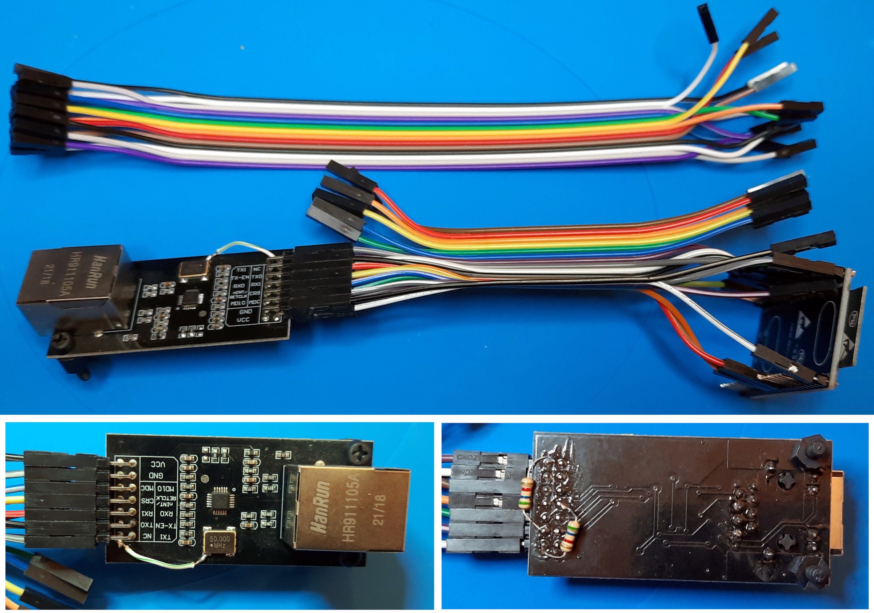
The initial attempt, redoing things with long and then short jumper wires
Finally I decided to remove that variable altogether and design a PCB based on the connections that were supposed to work, eventually transferring the pull up and down resistors to the PCB and requiring the crystal disable pin to be connected to the NC output as the single LAN8720 board mod. This PCB would be used for the RS485 transceiver too, and would be integrated in a cheap 3 module wide DIN rail case, so all around a useful use of my time. I'll share that tale a bit later.
I started to count the variables I had easy control of, and changing them one by one. First order of business are the software variants, as there are plenty of ways to connect ethernet transceivers to the ESP32 MCUs, as indicated by the documentation. Most notably, there's a clock selection, an oscilator enable signal, the I2C signal lines and address. The signal lines are well known, so we can just set and forget those. The address is either 0 or 1, we'll need to test with both until we get a positive reply.
The clock stuff is confusing, and I really don't know what to do other than copy what others have done at this point. So taking as a starting point a test sketch from the mentioned github issue:
/*
    This sketch shows how to configure different external or internal clock sources for the Ethernet PHY
*/

#include <ETH.h>

/*
   * ETH_CLOCK_GPIO0_IN   - default: external clock from crystal oscillator
   * ETH_CLOCK_GPIO0_OUT  - 50MHz clock from internal APLL output on GPIO0 - possibly an inverter is needed for LAN8720
   * ETH_CLOCK_GPIO16_OUT - 50MHz clock from internal APLL output on GPIO16 - possibly an inverter is needed for LAN8720
   * ETH_CLOCK_GPIO17_OUT - 50MHz clock from internal APLL inverted output on GPIO17 - tested with LAN8720
*/
#define ETH_CLK_MODE    ETH_CLOCK_GPIO17_OUT

// Pin# of the enable signal for the external crystal oscillator (-1 to disable for internal APLL source)
#define ETH_POWER_PIN   -1

// Type of the Ethernet PHY (LAN8720 or TLK110)
#define ETH_TYPE        ETH_PHY_LAN8720

// I²C-address of Ethernet PHY (0 or 1 for LAN8720, 31 for TLK110)
#define ETH_ADDR        1

// Pin# of the I²C clock signal for the Ethernet PHY
#define ETH_MDC_PIN     23

// Pin# of the I²C IO signal for the Ethernet PHY
#define ETH_MDIO_PIN    18


static bool eth_connected = false;

void WiFiEvent(WiFiEvent_t event) {
  switch (event) {
    case SYSTEM_EVENT_ETH_START:
      Serial.println("ETH Started");
      //set eth hostname here
      ETH.setHostname("esp32-ethernet");
      break;
    case SYSTEM_EVENT_ETH_CONNECTED:
      Serial.println("ETH Connected");
      break;
    case SYSTEM_EVENT_ETH_GOT_IP:
      Serial.print("ETH MAC: ");
      Serial.print(ETH.macAddress());
      Serial.print(", IPv4: ");
      Serial.print(ETH.localIP());
      if (ETH.fullDuplex()) {
        Serial.print(", FULL_DUPLEX");
      }
      Serial.print(", ");
      Serial.print(ETH.linkSpeed());
      Serial.println("Mbps");
      eth_connected = true;
      break;
    case SYSTEM_EVENT_ETH_DISCONNECTED:
      Serial.println("ETH Disconnected");
      eth_connected = false;
      break;
    case SYSTEM_EVENT_ETH_STOP:
      Serial.println("ETH Stopped");
      eth_connected = false;
      break;
    default:
      break;
  }
}

void testClient(const char * host, uint16_t port) {
  Serial.print("\nconnecting to ");
  Serial.println(host);

  WiFiClient client;
  if (!client.connect(host, port)) {
    Serial.println("connection failed");
    return;
  }
  client.printf("GET / HTTP/1.1\r\nHost: %s\r\n\r\n", host);
  while (client.connected() && !client.available());
  while (client.available()) {
    Serial.write(client.read());
  }

  Serial.println("closing connection\n");
  client.stop();
}

void setup() {
  Serial.begin(115200);
  WiFi.onEvent(WiFiEvent);
  ETH.begin(ETH_ADDR, ETH_POWER_PIN, ETH_MDC_PIN, ETH_MDIO_PIN, ETH_TYPE, ETH_CLK_MODE);
}


void loop() {
  if (eth_connected) {
    testClient("google.com", 80);
  }
  delay(10000);
}
We get to play with these macros:
#define ETH_CLK_MODE ETH_CLOCK_GPIO17_OUT
#define ETH_POWER_PIN -1
#define ETH_ADDR 1
First up, lets just upload the sketch to our ESP32 dev board and run as is, with no LAN8720 connected:
E (40) lan87xx: lan87xx_init(499): wrong chip ID
E (41) esp_eth: esp_eth_driver_install(215): init phy failed
That is our base line, now same script but with my previously modded LAN8720, which has tested working in the past:
E (120) lan87xx: lan87xx_pwrctl(409): power up timeout
E (120) lan87xx: lan87xx_init(491): power control failed
E (121) esp_eth: esp_eth_driver_install(215): init phy failed
Right, and changing ETH_ADDR to 0:
E (120) lan87xx: lan87xx_pwrctl(409): power up timeout
E (120) lan87xx: lan87xx_init(491): power control failed
E (121) esp_eth: esp_eth_driver_install(215): init phy failed
So this tells us two things:
- There's certainly some communication between the LAN8720 and the ESP32, as the "wrong chip ID" error is not present in the latter two tests
- Changing the I2C ID does nothing at this stage, so there's some other problem at work here
One thing that comes to mind is that I have not even looked at the arduino-esp32 support package version at all. There's definitely a bunch of changes that might potentially have changed things since I last tried this out, and the tests just completed have been done on Arduino 2.0.5 with arduino-esp 2.0.6. Maybe roll back the board support package? Lets try 1.0.6, the last of the 1.x line.
E (1009) emac: Timed out waiting for PHY register 0x2 to have value 0x0007(mask 0xffff). Current value 0xffff
E (2009) emac: Timed out waiting for PHY register 0x3 to have value 0xc0f0(mask 0xfff0). Current value 0xffff
E (2009) emac: Initialise PHY device Timeout
That is both addresses 0 and 1 showing the same as before, so while the output has changed a bit, I assume at this point it is the exact same issue. We will keep ourselves on the 1.0.6 version for now, and next I'll play around with the clock part.
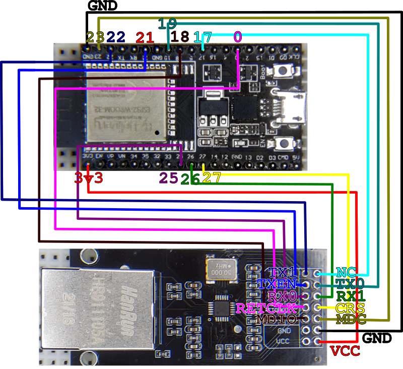
The wiring between MCU and Transceiver, as used at this point
There are two pins being used for this, GPIOs 0 and 17, and the crystal disable is connected to pin 17, so ETH_CLOCK_GPIO17_OUT seems unlikely. From what I can understand, that means we are outputting a 50MHz signal from the ESP32 on this pin, which is not really consistent with how we have it wired. My best guess would be:
#define ETH_CLK_MODE ETH_CLOCK_GPIO0_IN
#define ETH_POWER_PIN 17
The idea is that during bootup the LAN8720 crystal is disabled, as that seems to be a requirement to successfully bootstrap the transceiver as indicated in the "The clock issue" section of Sautter's blog entry, and then when the disable signal is removed, we use its clock signal to sync things, and we are getting that signal in GPIO0. Makes some sense... address 0 gave me the same result as above, but address 1:
ETH Started
ETH Connected
ETH MAC: C0:49:EF:CE:28:4B, IPv4: 192.168.1.207, FULL_DUPLEX, 100Mbps
connecting to google.com
HTTP/1.1 301 Moved Permanently
Success at last! So to recap we are using
#define ETH_CLK_MODE ETH_CLOCK_GPIO0_IN
#define ETH_POWER_PIN 17
#define ETH_TYPE ETH_PHY_LAN8720
#define ETH_ADDR 1
#define ETH_MDC_PIN 23
#define ETH_MDIO_PIN 18
And the next logical step is to try this out with the latest arduino-esp32 version, which is 2.0.6. Installed that, reflashed the board and...
Nothing. I mean, there's the usual at boot debug stuff, so I know the board is running, just no message. Ok, that just means we don't have enough debug implemented :), so lets add a bit around the ethernet setup function.
void setup() {
  Serial.begin(115200);
  WiFi.onEvent(WiFiEvent);
  Serial.println("Starting ETH");
  ETH.begin(ETH_ADDR, ETH_POWER_PIN, ETH_MDC_PIN, ETH_MDIO_PIN, ETH_TYPE, ETH_CLK_MODE);
  Serial.println("Started ETH");
}
Running this slightly tweaked version shows both new lines of debug we introduced, but nothing in between, so the ethernet driver is initializing just fine, only we're not getting any event callbacks afterwards.
Starting ETH
Started ETH
Oh, I think I know what this is, the system event names have changed. For some reason that does not trigger any error, i.e. the old events are still defined just not used anymore, which is odd, but that is not where I want my focus to be directed to, so lets check what these are called now. The change happened when the arduino-esp code had the ESP-IDF library updated to version 4.4, as indicated in this (huge, colossal) commit: https://github.com/espressif/arduino-esp32/commit/5502879a5b25e5fff84a7058f448be481c0a1f73
The gist of it for our purposes is SYSTEM_EVENT_* events were renamed ARDUINO_EVENT_*, so lets try that:
Starting ETH
ETH Started
ETH Connected
ETH MAC: C0:49:EF:CE:28:4B, IPv4: 192.168.1.207, FULL_DUPLEX, 100Mbps
Started ETH
connecting to google.com
HTTP/1.1 301 Moved Permanently
Woot, we have this working on the latest version of the BSP, below is a reproduction of the final test sketch:
/*
    This sketch shows how to configure different external or internal clock sources for the Ethernet PHY
*/

#include <ETH.h>

/*
   * ETH_CLOCK_GPIO0_IN   - default: external clock from crystal oscillator
   * ETH_CLOCK_GPIO0_OUT  - 50MHz clock from internal APLL output on GPIO0 - possibly an inverter is needed for LAN8720
   * ETH_CLOCK_GPIO16_OUT - 50MHz clock from internal APLL output on GPIO16 - possibly an inverter is needed for LAN8720
   * ETH_CLOCK_GPIO17_OUT - 50MHz clock from internal APLL inverted output on GPIO17 - tested with LAN8720
*/
#define ETH_CLK_MODE    ETH_CLOCK_GPIO0_IN

// Pin# of the enable signal for the external crystal oscillator (-1 to disable for internal APLL source)
#define ETH_POWER_PIN   17

// Type of the Ethernet PHY (LAN8720 or TLK110)
#define ETH_TYPE        ETH_PHY_LAN8720

// I²C-address of Ethernet PHY (0 or 1 for LAN8720, 31 for TLK110)
#define ETH_ADDR        1

// Pin# of the I²C clock signal for the Ethernet PHY
#define ETH_MDC_PIN     23

// Pin# of the I²C IO signal for the Ethernet PHY
#define ETH_MDIO_PIN    18


static bool eth_connected = false;

void WiFiEvent(WiFiEvent_t event) {
  switch (event) {
    case ARDUINO_EVENT_ETH_START:
      Serial.println("ETH Started");
      //set eth hostname here
      ETH.setHostname("esp32-ethernet");
      break;
    case ARDUINO_EVENT_ETH_CONNECTED:
      Serial.println("ETH Connected");
      break;
    case ARDUINO_EVENT_ETH_GOT_IP:
      Serial.print("ETH MAC: ");
      Serial.print(ETH.macAddress());
      Serial.print(", IPv4: ");
      Serial.print(ETH.localIP());
      if (ETH.fullDuplex()) {
        Serial.print(", FULL_DUPLEX");
      }
      Serial.print(", ");
      Serial.print(ETH.linkSpeed());
      Serial.println("Mbps");
      eth_connected = true;
      break;
    case ARDUINO_EVENT_ETH_DISCONNECTED:
      Serial.println("ETH Disconnected");
      eth_connected = false;
      break;
    case ARDUINO_EVENT_ETH_STOP:
      Serial.println("ETH Stopped");
      eth_connected = false;
      break;
    default:
      break;
  }
}

void testClient(const char * host, uint16_t port) {
  Serial.print("\nconnecting to ");
  Serial.println(host);

  WiFiClient client;
  if (!client.connect(host, port)) {
    Serial.println("connection failed");
    return;
  }
  client.printf("GET / HTTP/1.1\r\nHost: %s\r\n\r\n", host);
  while (client.connected() && !client.available());
  while (client.available()) {
    Serial.write(client.read());
  }

  Serial.println("closing connection\n");
  client.stop();
}

void setup() {
  Serial.begin(115200);
  WiFi.onEvent(WiFiEvent);
  Serial.println("Starting ETH");
  ETH.begin(ETH_ADDR, ETH_POWER_PIN, ETH_MDC_PIN, ETH_MDIO_PIN, ETH_TYPE, ETH_CLK_MODE);
  Serial.println("Started ETH");
}


void loop() {
  if (eth_connected) {
    testClient("google.com", 80);
  }
  delay(10000);
}
But wait, there's more
This is where I should have left it, after all it is working and that's great. However, I still have some questions regarding the ability to run this with jumper wires, which is not really important but hey, inquiring minds and such. Also I'm torn as to how much of this we just did is still required for the updated BSP, and so I must start afresh. The plan is to start with version 2.0.6 of arduino-esp32 and an unmodded LAN8720 using long jumper wires and work my way to something useful, one step at a time. There's one thing that I didn't mention, the last time I did this I remember having to reset the board while holding the "boot" button to get it to program, and with the current dev boards I'm using that is no longer required. This means something around GPIO0, the one connected to the boot button, may have changed, so it is worth trying this from the beginning.
Same ESP32, a pristine LAN8720 without any changes, the same wires connected except for the GPIO17 <-> NC since there's nothing on the NC pin at the moment, I upload the same sketch and:
Starting ETH
ETH Started
ETH Connected
Started ETH
ETH MAC: C0:49:EF:CE:28:4B, IPv4: 192.168.1.207, FULL_DUPLEX, 100Mbps
connecting to google.com
HTTP/1.1 301 Moved Permanently
So, no need for any change anymore? Maybe, except every now and then I get:
rst:0x1 (POWERON_RESET),boot:0x3 (DOWNLOAD_BOOT(UART0/UART1/SDIO_REI_REO_V2))
waiting for download
That actually makes some sense, as we removed the pull up resistor from GPIO0. Well, we didn't add it, but yes, removed when compared to the previously working version of this thing. However adding it didn't make any change, if anything it anecdotally slightly increased the frequency of bootloader entries.
This may mean I need a stronger pull up in the form of a smaller resistance, but just to assert this is indeed the issue I remove the connection from the ESP32 completely, so no REFCLK line. This will surely prevent the transceiver from working but will tell me if anything else is preventing the normal boot for the ESP32:
Starting ETH
E (1010) esp.emac: emac_esp32_init(349): reset timeout
E (1010) esp_eth: esp_eth_driver_install(214): init mac failed
Started ETH
Ok, as expected the lack of the clock signal does prevent proper initialization, and in fact no more upload bootloader appears. There's one detail I just realized; if we don't need GPIO17, the crystal disable, then the timing issues mentioned in the fora must have been resolved along the way in firmware, and we can safely not connect that pin and #define ETH_POWER_PIN -1.
Before I start trying to find the idea pull up resistor, just for giggles, I'll try to not depend on the external clock by pretending we are sending one from ESP32 to LAN8720. Pretending as in all likeliness the ESP32 will generate the clock on the pin assigned but we are not routing that signal at all, so with #define ETH_CLOCK_MODE ETH_CLOCK_GPIO0_OUT:
Starting ETH
ETH Started
ETH Connected
ETH MAC: C0:49:EF:CE:28:4B, IPv4: 192.168.1.207, FULL_DUPLEX, 100Mbps
Started ETH
connecting to google.com
HTTP/1.1 301 Moved Permanently
Which would imply we don't need the clock sync at all, but in reality, from my limited manual testing, there is a very defined difference in responsiveness between having the clock being fed into the ESP32 or not, and my best guess is that there's a good error correction algorithm being used and with enough retries the two parties can communicate fairly well, but not as well as with the clock being shared. I have no evidence to support that theory, and it might just be that the REFCLK line is only needed if the transceiver does not have its own clock generator, depending on the MCU. Still, I might dig a little deeper onto this by reading the LAN8720 datasheet, but for now I have a working version and I really wanted to share one more thing in this post, as hinted at the very start of it;
The PCB, a story of 3 revisions
I have a small assortment of DIN Rail mountable cases, in different widths, for Raspberry PIs or generic project boxes. The latter type is what I had my eye for on this project.
We're talking cheap, no name things, likely not as "fire resistant" as one would be required to have for actual mains distribution box installations, both for building code reasons which will depend on where you live but mostly because, you know, fire's great to cook stuff, but if you're not careful it will cook ALL your stuff. So, even though there will be a little forethought on eventually powering this from mains power, that is definitely not what I'll be doing in this instance and the end result will be kept well separated from any mains level power.
Since I'm aiming for having the ESP32 dev board on a socket and the RS485 on another, I used the widest DIN Rail box I have handy, a 3 module wide one to be exact. Next steps were obviously tracing the inner dimensions to design a PCB accordingly, with positions for screw terminals.
The LAN transceiver board was a little more convoluted... it is too high and long to fit fully inside the case which is just as well, I would always need to make a hole somewhere to expose the connector, so my estimation was that sitting it above the ESP32 with some sort of riser board would allow for just enough space to have the connector protruding ever so slightly on the side, provided I made a hole in the right spot, of course.
And so I grabbed Kicad, made a simple schematic with connectors for the pinout of the ESP32, RS485 transceiver and LAN8720. I didn't use proper symbols at all, just generic connectors with the net names on the appropriate pin connections. I did add a couple of resistors for the pull up and pull down I thought at this point would be required. This was the board I made all my testing with as described in this entry.
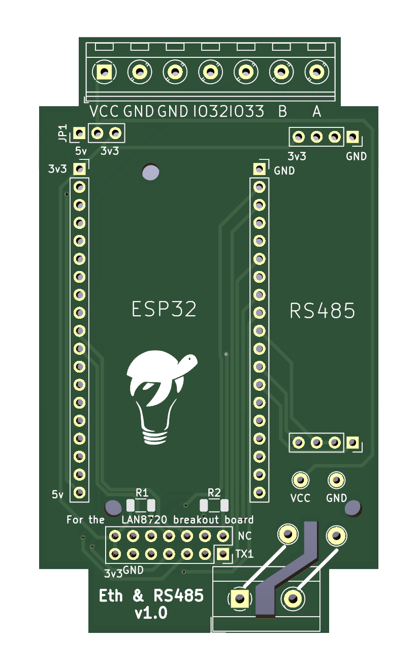
A render for first version of the PCB
The PCB came out pretty enough, I added connections for the screw terminals to have the needed signals accessible from the outside, all professional and such! I even went so far as to add a jumper to select if we are supplying 5v or 3.3v to the ESP32, as the RS485 transceiver will be supplied with 3.3v, and this may come from the ESP's LDO if we are feeding 5v in, or directly for the external 3.3v line, if that's what we have.
Also, I thought I might want to add one of those small power supplies inside the case so we can supply mains directly, so I made a place to connect the 220v that simply goes to a couple of test points, to which one would solder the power supply's input, with another set of test points connected to the main power rail for the output.
The end result? It was ok, the fit inside the case was pretty much perfect, I soldered the connectors in their respective places, didn't add the resistors since I was planning on using the already modded LAN board for initial testing, and the rest is documented above.
There were, however, a few kinks to iron out;
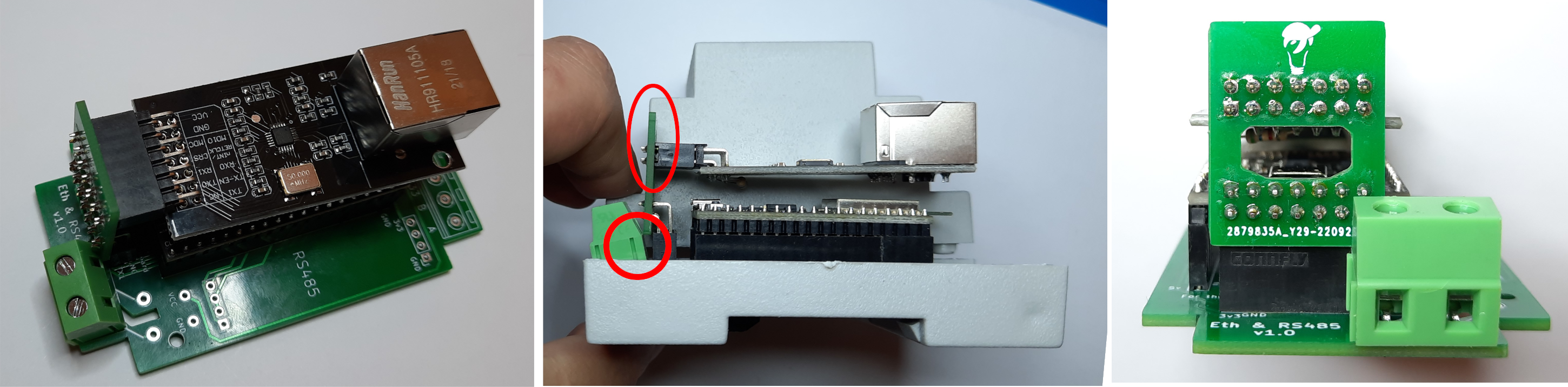
A good view of what I got wrong on the first version
The position of the LAN riser connector and the design of the riser proper presents a couple of problems, as indicated on the middle image above, for it is too far back on the case to fit inside it, even if we cut a hole for the connector as it is the opposite side that is wrongly placed. Also the screw terminal for mains connection will not sit as it bangs against the LAN connector.
The right image shows a less important but still quite annoying issue, as I had left a hole on the riser PCB to allow connecting the ESP32 through USB do power, program and debug with the LAN board attached and not only the hole is too small for any micro USB cable I own, it is also, and this is subtle I know, not ideally located.
So back to the drawing, ahm, screen, I guess?
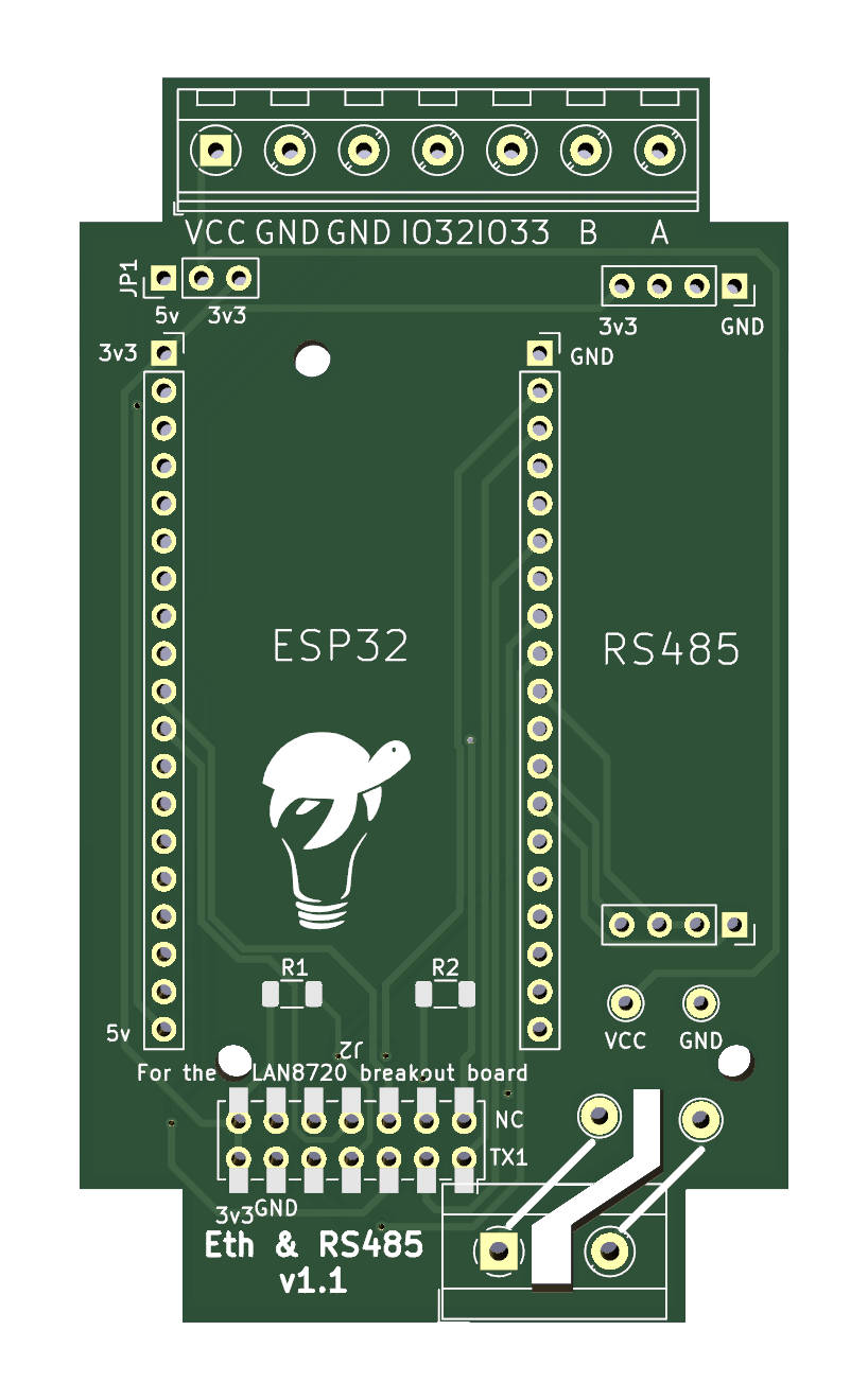
A render for the second version PCB
Version 1.1 has a new connector footprint for the riser card, one that allows for a low height SMD connector that still allows for pins to be pushed through. It is actually a hybrid design using a through hole footprint overlaid with the SMD one. This allows for lower sitting of the riser card on the main PCB, so we can dig a larger hole that maybe actually allows passage of the micro USB connector. An ever so slight repositioning of the connector should also allow for the mains terminal to fully sit on the PCB.
The riser card suffered a few changes too, by connecting it on the opposite side of the main PCB connector, so closer to the ESP32 and away from the offending case wall, along with a much larger hole and, to allow the same relative position of the LAN card on top of the ESP32, the use of the hybrid connection mentioned before, with the connector soldered on the back, i.e. the opposite side from where the LAN card gets connected to.
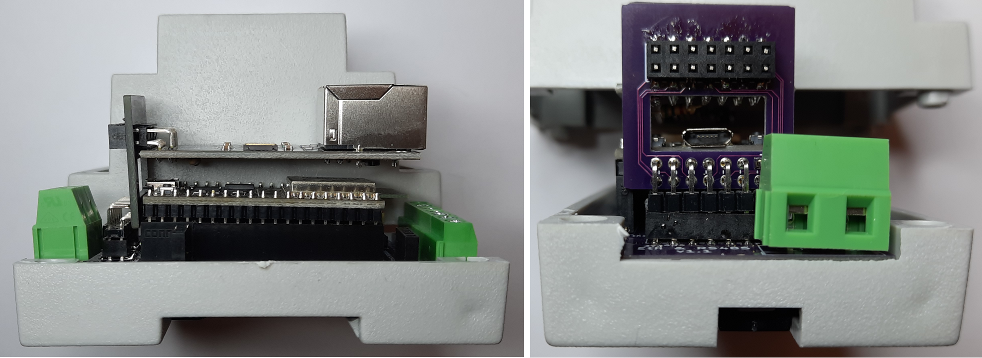
The second version came out so much better.
And just to check everything fits, I set out to cut a hole on the case so the RJ45 connector could protrude... And of course I measured and eyeballed and took a pencil and made a square approximately where the hole should be, grabbed my rotary cutting tool and;
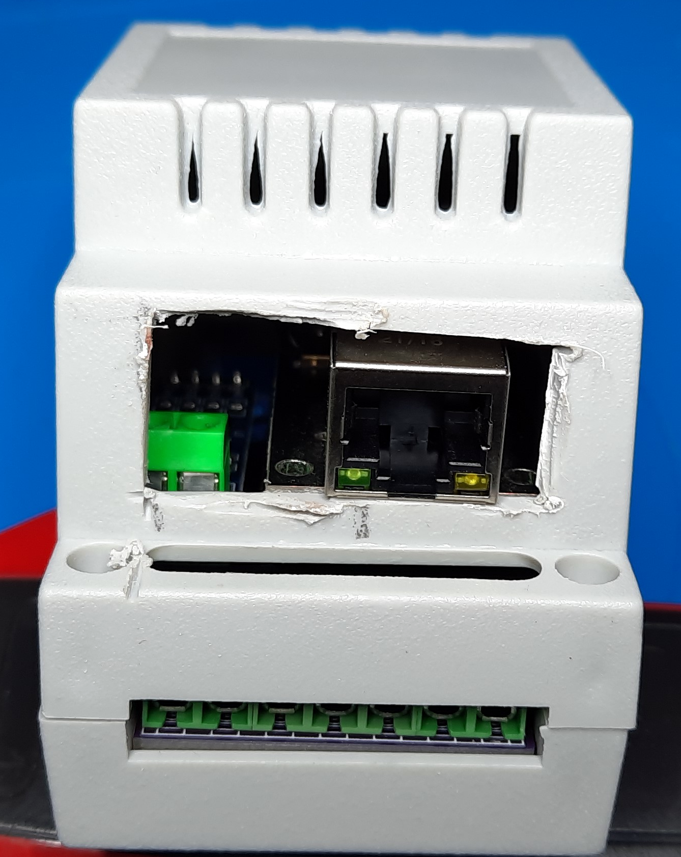
Well, it fits ;)
Of course I somehow managed to sketch the hole on the wrong side, and much larger than needed. But yeah, at least there's plenty of air flow. And it does fit snugly as designed so that's something.
The third version, which I have ordered but not yet received, is exactly the same as the previous except for a couple of solder links on the NC and RETCLK lines, so we can leave them unconnected. I still need to find the proper resistor value for the pull up on GPIO0 / RETCLK to allow for the clock to be shared but also avoid the bootloader flash upgrade mode entry.
A post scriptum of sorts
As I wrapped this little experiment and was proof reading the brain dump thereof, or as I like to call it "This journal entry", I thought it would be in bad manner to not have the resistor value chosen for the GPIO0 <-> RETCLK pull up, so I started from where I was in my initial testing, 5.6KΩ, and start working my way down to the highest resistance that would prevent the bootloader update mode. I went down to 2.2KΩ and was starting to feel a little discomfort, something felt wrong to be able to go that low and still have a 50% bootloader update mode entry chance.
And then it hit me... with everything connected, both GPIO17 as a power up crystal disable signal and GPIO0 receiving the oscillator output from the LAN transceiver thought the modded NC connection, there was a 100% chance of a proper bootup, while still allowing for bootloader update if the boot button was pressed on reset. And I decided based on a bunch of false assumptions that there was no need for that disable signal, as I was getting everything running perfect when it booted properly. And therein lies the detail I missed; It fails to boot properly because the RETCLK pin is already carrying the oscillator output, thus pulling the signal up and down and up and down and... you get the picture. Funny thing, this is actually spelled out in no uncertain way in the same blog entry I used as a guide for the project, I must have read it a good dozen times, but I don't know if I have mentioned it before, I forget...
Of course we need the disable signal if we are to use the ETH_CLOCK_GPIO0_IN mode. This does not mean we can't just leave both oscillator input and disable pin disconnected, we know that works at least partially and I will do some further testing on that, but for the proper, actually known to work as expected solution, we need both lines and both the pull up and pull down resistors.
I considered editing this whole article to avoid steering anyone following this text as an instructional piece in the wrong direction, but if you are taking any of my articles as tutorials, well, you deserve what you get :) This sequential "type it as I think it" workflow is a lot more conductive to carrying a valuable lesson on how to get there, rather than just showing a picture of the destination. If ever I had a lesson to teach, that is.
You can find both the Arduino code and the PCB sources for Kicad on this post's github repository.